
Method, computer program and device for monitoring a vacuum device

Inactive Publication Date: 2003-01-09
ROBERT BOSCH GMBH
View PDF6 Cites 51 Cited by
  • Summary
  • Abstract
  • Description
  • Claims
  • Application Information

AI Technical Summary

Problems solved by technology

Usually, the vacuum in the vacuum chamber is in fact taken from an intake tube of the internal combustion engine; in certain cases, it is possible that the existing vacuum in the intake tube of the internal combustion engine is not sufficient to produce enough vacuum in the vacuum chamber to operate the servo unit.
Sensors of this kind, though, are expensive and are themselves susceptible to malfunction.

Method used


Image

  • Method, computer program and device for monitoring a vacuum device
  • Method, computer program and device for monitoring a vacuum device
  • Method, computer program and device for monitoring a vacuum device

Examples


Embodiment Construction

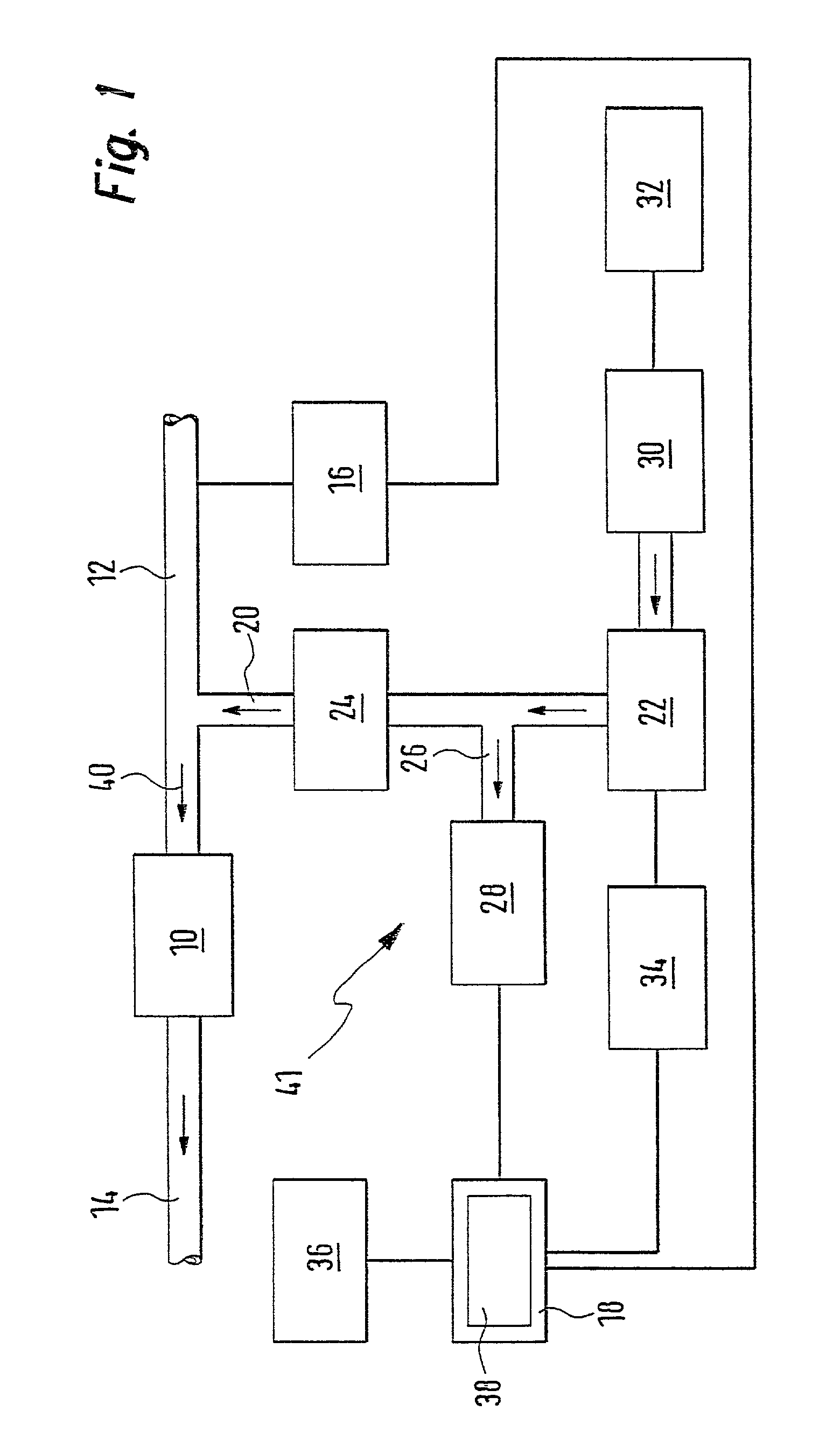
[0042] In FIG. 1, an internal combustion engine is labeled with the reference numeral 10. It is supplied with air (arrow 40) from an intake line 12 and the exhaust gases are carried off by means of an exhaust line 14. The pressure in the intake line 12 is measured by a pressure sensor 16, which uses a data line (no reference numeral) to send signals to a set of control electronics 18.

[0043] A vacuum chamber 22 is fluid-connected to the intake tube 12 by means of a suction line 20. Between the vacuum chamber 22 and the intake tube 12, a check valve 24 is provided, which permits a flow only from the vacuum chamber 22 to the intake tube 12.

[0044] Between the vacuum chamber 22 and the check valve 24, a branch line 26 leads from the suction line 20 to an electric suction pump 28. This pump in turn is controlled by the control electronics 18 via a control line (no reference numeral).

[0045] The vacuum chamber 22 is fluid-connected to a brake booster 30, which represents a servo unit and is...


PUM


Abstract

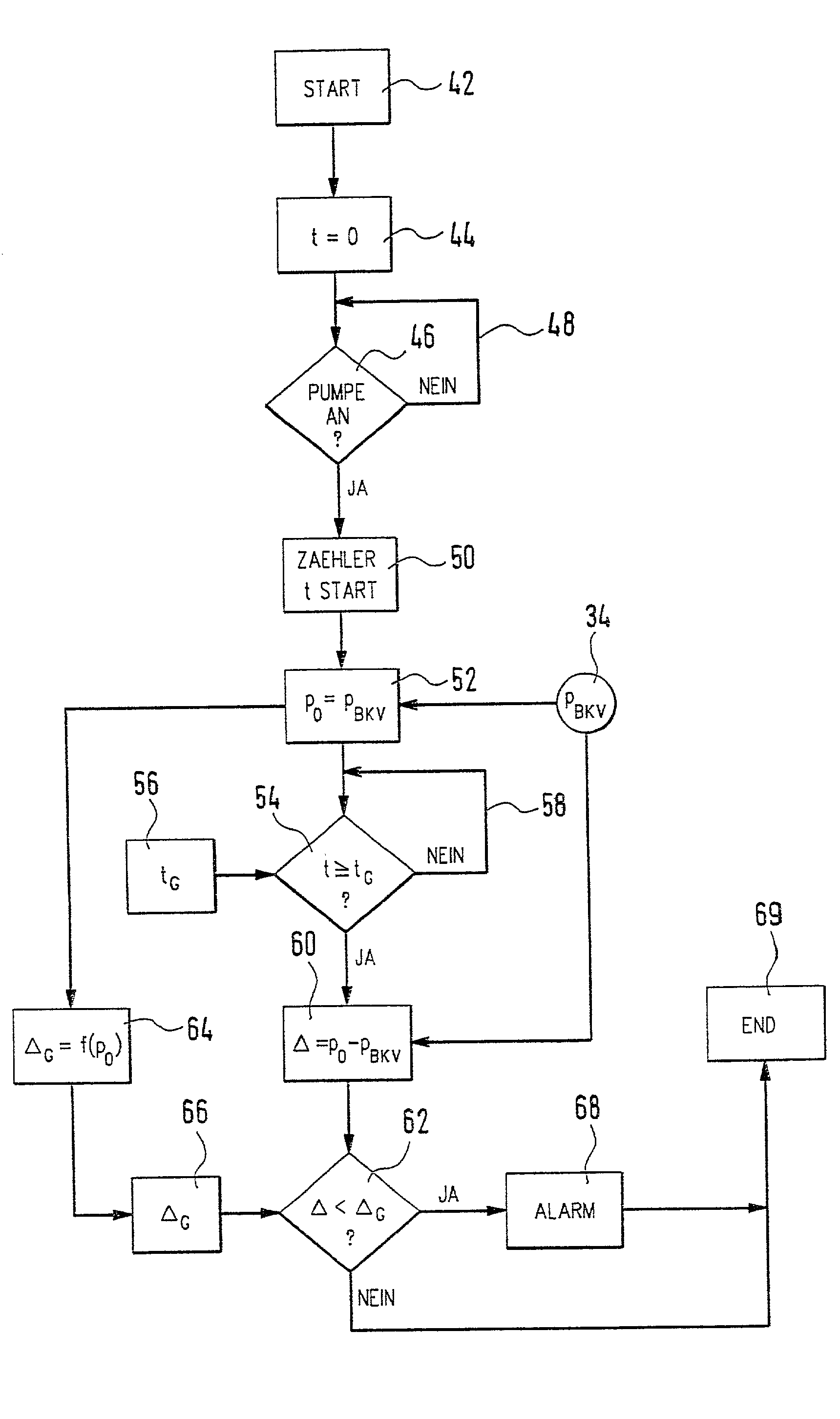
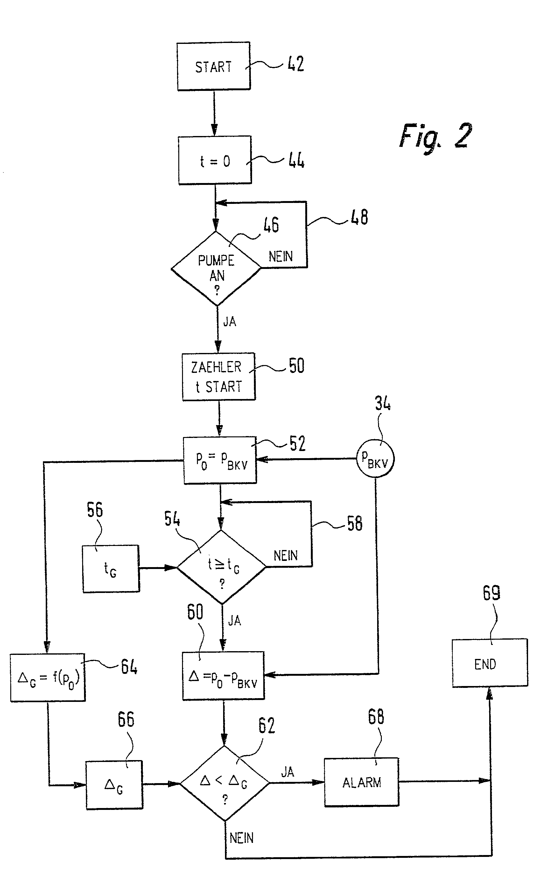
A vacuum chamber (22) of a pneumatically operated servo unit (30) of a motor vehicle is subjected to vacuum by an electric suction pump (28). In order to monitor the vacuum chamber (22) and the electric suction pump (28), the invention proposes that a starting pressure in the vacuum chamber (22) be determined. In addition, after a certain time interval, an ending pressure in the vacuum chamber (22) is determined. Furthermore, the difference between the ending pressure and the starting pressure is calculated and compared to a limit value. If this difference falls below the limit value, a signal is generated, in particular a warning and / or alarm signal.

Description

PRIOR ART[0001] The current invention relates to a method for monitoring a vacuum device of a pneumatically operated servo unit of a motor vehicle in which an electric suction pump exerts vacuum on a vacuum chamber.[0002] A method of the type mentioned at the beginning is used, for example, to monitor the vacuum device of a brake booster. Usually, the vacuum in the vacuum chamber is in fact taken from an intake tube of the internal combustion engine; in certain cases, it is possible that the existing vacuum in the intake tube of the internal combustion engine is not sufficient to produce enough vacuum in the vacuum chamber to operate the servo unit. For these cases, an electric suction pump is provided, which can be switched on in order to correspondingly act on the vacuum chamber.[0003] If the suction pump fails or if a leakage occurs in the system, this could up till now only be detected by means of additional sensors, which also detect the pressure, for example, in the electric s...

Claims


Application Information

Patent Timeline
IPC IPC(8): B60T13/46B60T17/02B60T17/22
CPCB60T13/46B60T17/02B60T17/22
Inventor WILD, ERNSTEBERLE, KRISTINAREUSCHENBACH, LUTZ
Owner ROBERT BOSCH GMBH
Learn More