Eureka AIR delivers breakthrough ideas for toughest innovation challenges, trusted by R&D personnel around the world.

Method and system for atrial capture detection based on far-field R-wave sensing

Inactive Publication Date: 2002-12-05
MEDTRONIC INC
View PDF3 Cites 71 Cited by
  • Summary
  • Abstract
  • Description
  • Claims
  • Application Information

AI Technical Summary

Benefits of technology

[0012] The present invention is therefore directed to providing a system and method for determining an atrial capture threshold. The system of the present invention overcomes the problems, disadvantages and limitations of the prior art described above, and provides a more efficient and accurate means of determining an atrial capture threshold.
[0014] In comparison to known techniques for determining an atrial capture threshold, various embodiments of the present invention provide one or more of the following advantages: (a) the ability to perform frequent, automatic threshold tests; (b) the ability to detect atrial capture by atrial sensing when the polarization signal is relatively large; (c) the ability to detect atrial capture by atrial sensing using the Far Field R-Wave, rather than ventricular sensing; and (d) the ability to perform threshold testing while maintaining regular pacing to the patient.

Problems solved by technology

Those problems include, without limitation: (a) difficulty in measuring the atrial evoked response because the atrial evoked response may be masked by polarization signals, (b) need to measure the atrial evoked response in close proximity to the atrial pacing pulse; (c) infrequent threshold testing, because the threshold test is a time-consuming, manual test that can only be performed in the hospital, (d) need for a ventricular lead using ventricular activity to sense atrial capture, (e) need for special low polarization electrodes to measure atrial evoked response without masking by polarization signals, and (f) need for triphasic test pulses to measure atrial evoked response without masking by polarization signals.

Method used


Image

  • Method and system for atrial capture detection based on far-field R-wave sensing
  • Method and system for atrial capture detection based on far-field R-wave sensing
  • Method and system for atrial capture detection based on far-field R-wave sensing

Examples


Embodiment Construction

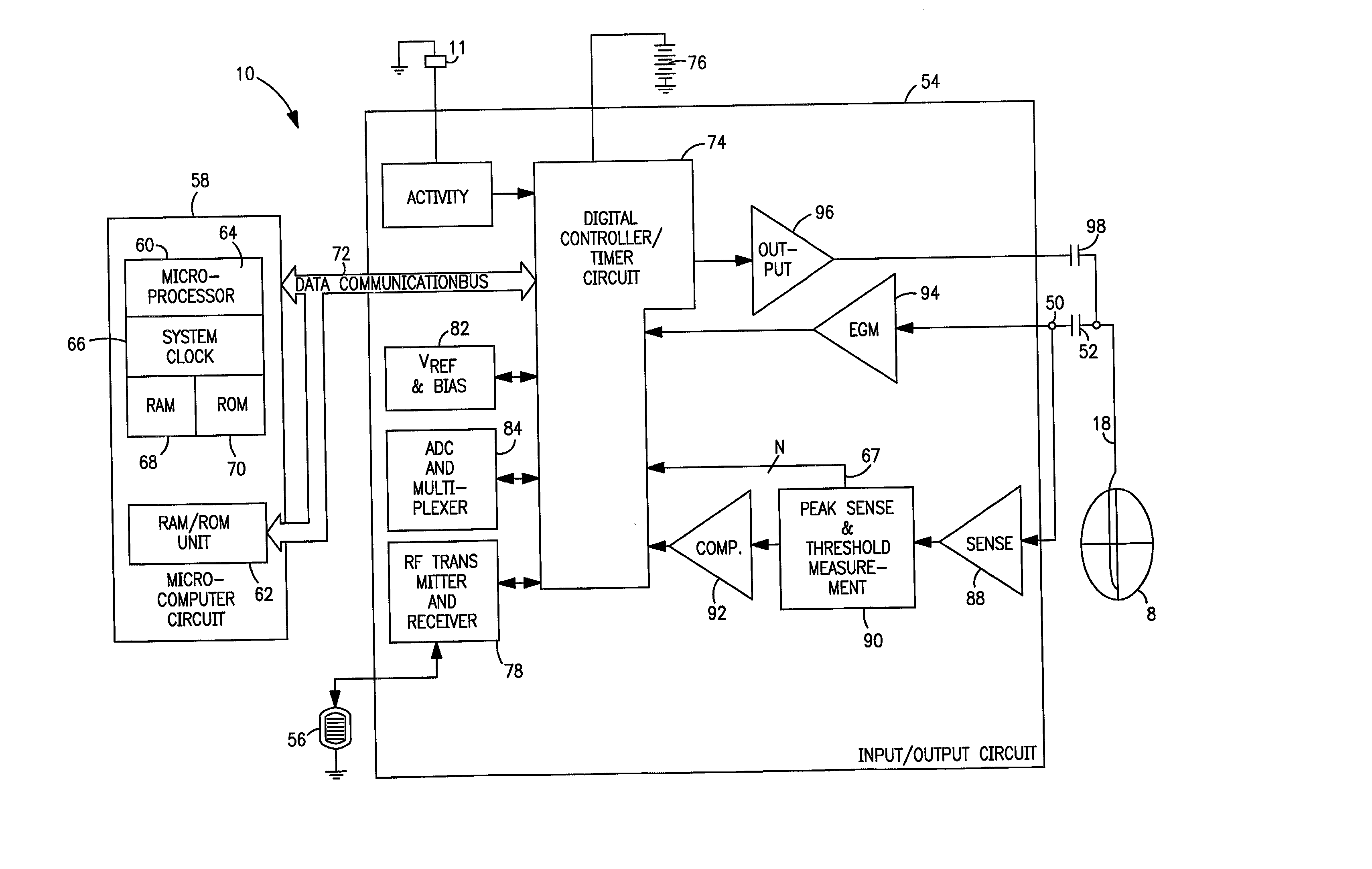
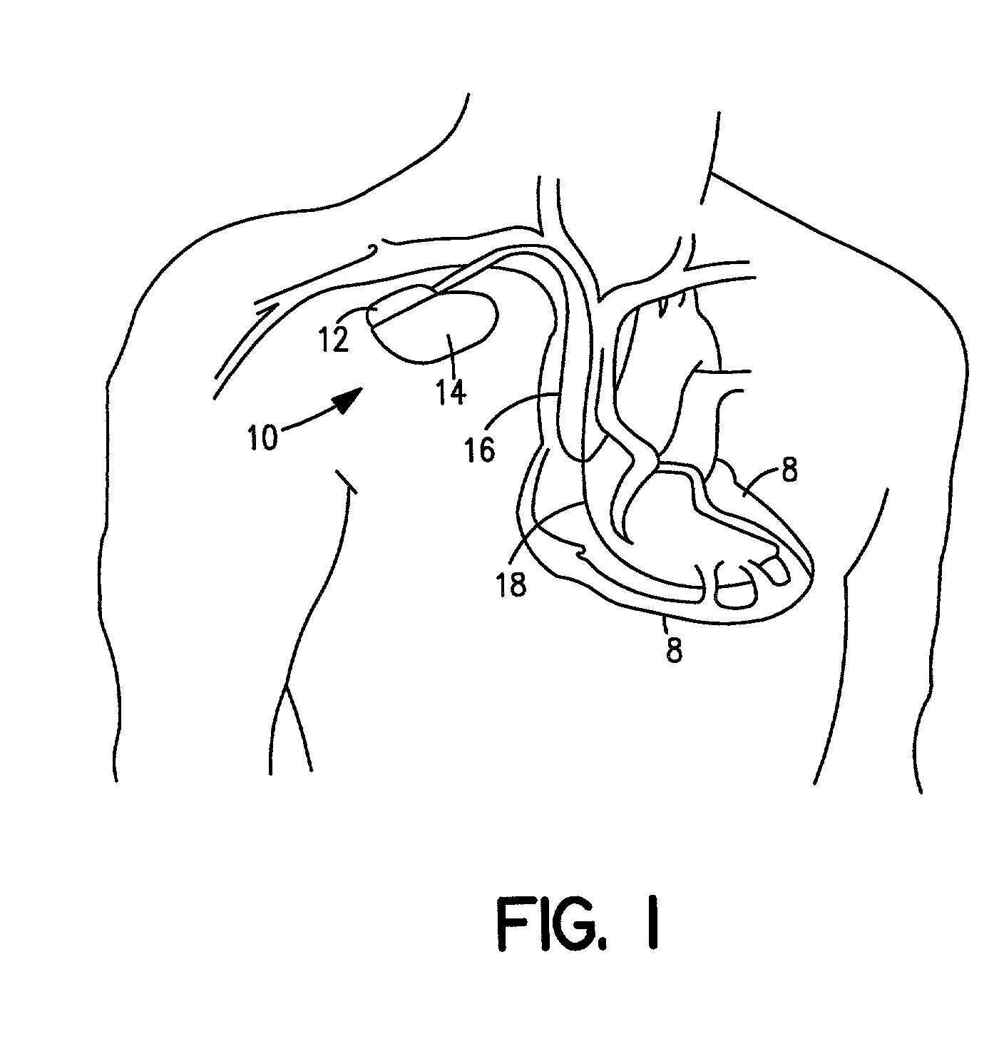
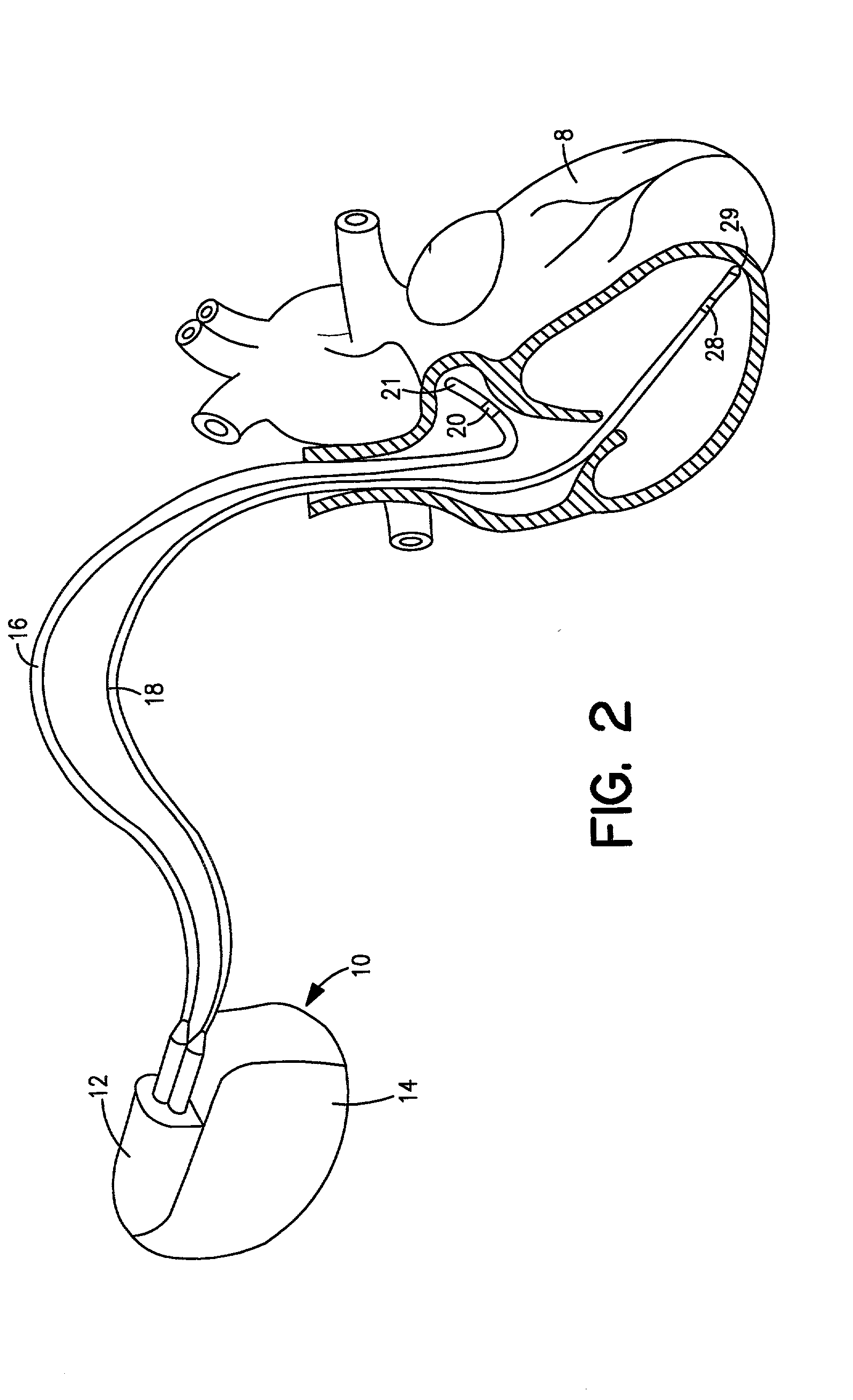
[0028] FIG. 1 is a simplified schematic view of one embodiment of implantable medical device ("IMD") 10 of the present invention. IMD 10 shown in FIG. 1 is a pacemaker comprising at least one of pacing and sensing leads 16 and 18 attached to hermetically sealed enclosure 14 and implanted near human or mammalian heart 8. Pacing and sensing leads 16 and 18 sense electrical signals attendant to the depolarization and re-polarization of the heart 8, and further provide pacing pulses for causing depolarization of cardiac tissue in the vicinity of the distal ends thereof. Leads 16 and 18 may have unipolar or bipolar electrodes disposed thereon, as is well known in the art. Examples of IMD 10 include implantable cardiac pacemakers disclosed in U.S. Pat. No. 5,158,078 to Bennett et al., U.S. Pat. No. 5,312,453 to Shelton et al. or U.S. Pat. No. 5,144,949 to Olson, all hereby incorporated by reference herein, each in its respective entirety.

[0029] FIG. 2 shows connector module 12 and hermeti...


PUM


Abstract

A method and system for atrial capture detection based on far-field R-wave (FFRW) sensing is provided. After establishing that stable FFRW sensing exists, presence of atrial capture can be detected by atrial sensing of the FFRW in a predetermined FFRW detection window following an atrial pace. Threshold values for the atrial pace can be determined by varying an atrial test variable and observing whether a FFRW occurs in the FFRW detection window. In another embodiment, threshold values for the atrial pace can be determined by applying a search pace before the regular atrial pace, varying an atrial test variable for the search pace, and monitoring the movement of the FFRW between the FFRW detection window and a predetermined search detection window located before the FFRW detection window.

Description

[0001] The present invention relates to the field of implanatable medical devices. More particularly, to cardiac pacing systems having atrial capture detection based on far-field R-wave sensing.[0002] Implantable cardiac pacing systems deliver a pacing pulse of sufficient amplitude and width to stimulate the heart. The pacing pulse must be above a threshold value before the heart tissue will respond. Although a pulse much greater than the threshold will evoke a response, a large energy pulse will deplete the implanted battery faster than a pulse just above the threshold. It is desirable to use a pacing pulse that is as small as safely required, one equal to the threshold times a safety factor. The threshold must be measured from time to time, because it changes with such factors as inflammation and fibrous tissue buildup near the electrode of the pacing system, medication, and the patient's general health. Currently, the threshold test must be performed at a hospital during a time-c...

Claims


Application Information

Patent Timeline
IPC IPC(8): A61N1/37
CPCA61N1/3712A61N1/3716A61N1/3714
Inventor VONK, BEN F. M.
Owner MEDTRONIC INC
Why Eureka
Eureka Blog
Learn More