
Method and workstation for generating virtual tooth models from three-dimensional tooth data

Active Publication Date: 2002-12-05
ORAMETRIX
View PDF36 Cites 133 Cited by
  • Summary
  • Abstract
  • Description
  • Claims
  • Application Information

AI Technical Summary

Problems solved by technology

However, it is obvious that such an approach requires an extreme amount of time and labor, and this is the reason why it is limited to scientific environments like orthodontic schools and universities.
While at the beginning of treatment things generally run well as all teeth start to move at least into the right direction, at the end of treatment a lot of time is lost by adaptations and corrections required due to the fact that the end result has not been properly planned at any point of time.
And the patient has no choice and does not know that treatment time could be significantly reduced if proper planning was done.
As noted in the Massen et al. patent, the Brandestini et al. technique is difficult to use when there are large variations in surface topography since such large jumps displace the pattern by an amount larger than the phase constant of the pattern, making it difficult to reconstruct the pattern of lines.
The system of the '281 patent is not particularly flexible, since it requires the object to be placed on the rotational stage and precise control of the relative position of the object and the positioning head is required at all times. It is unsuited for in vivo scanning of the teeth.
Neither of the techniques of Andreiko have met with commercial success or acceptance in orthodontics.
Moreover, the video technique does not produce complete three-dimensional information as to the teeth, but rather a limited amount of two-dimensional information, requiring significant operator input.
While this information may be useful for evaluating the current situation, or even designing an implant, it is not directly useable in orthodontic treatment planning since the teeth are not represented as individual objects.

Method used


Image

  • Method and workstation for generating virtual tooth models from three-dimensional tooth data
  • Method and workstation for generating virtual tooth models from three-dimensional tooth data
  • Method and workstation for generating virtual tooth models from three-dimensional tooth data

Examples


Embodiment Construction

[0090] Part 1. Overview

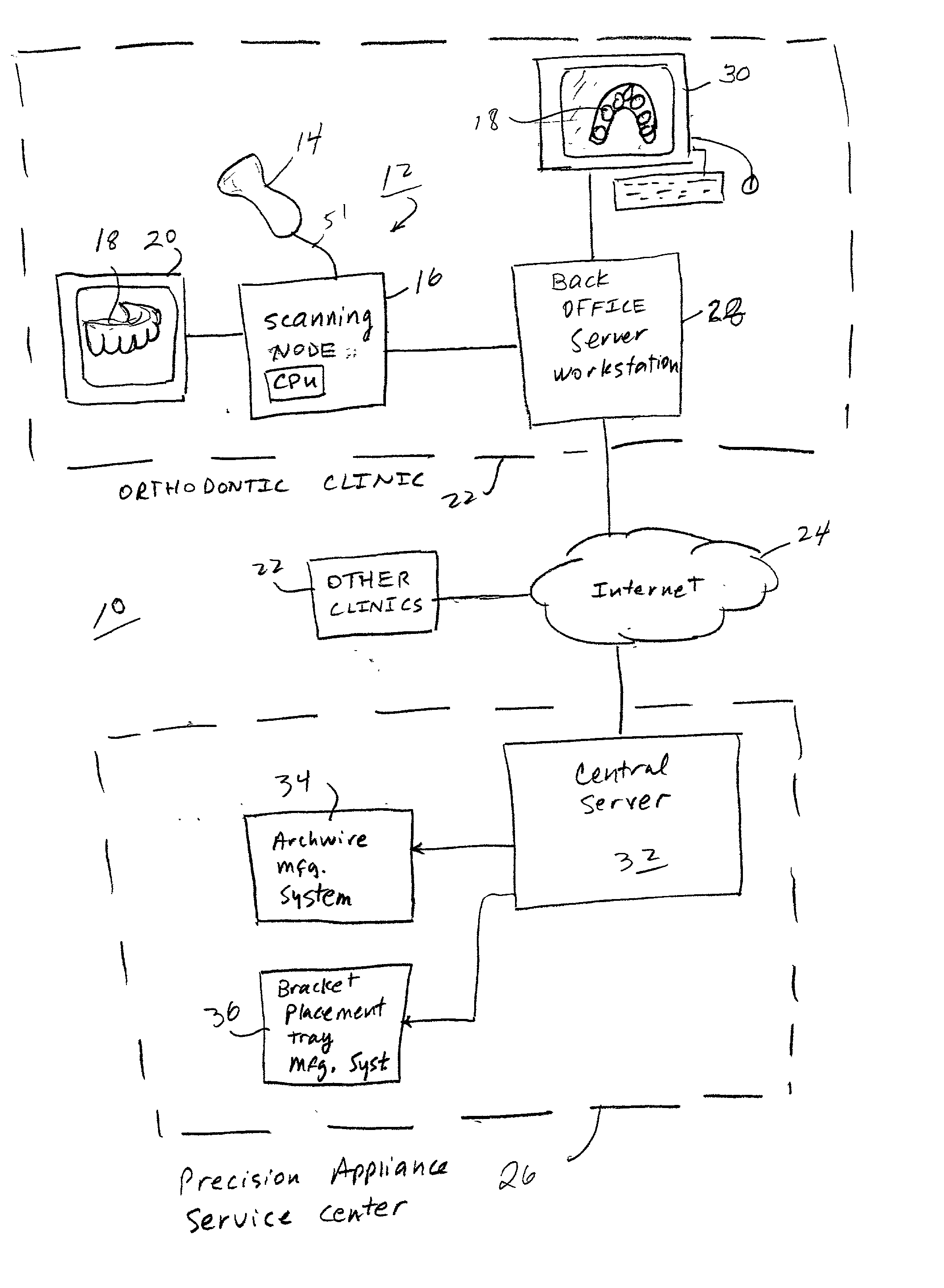
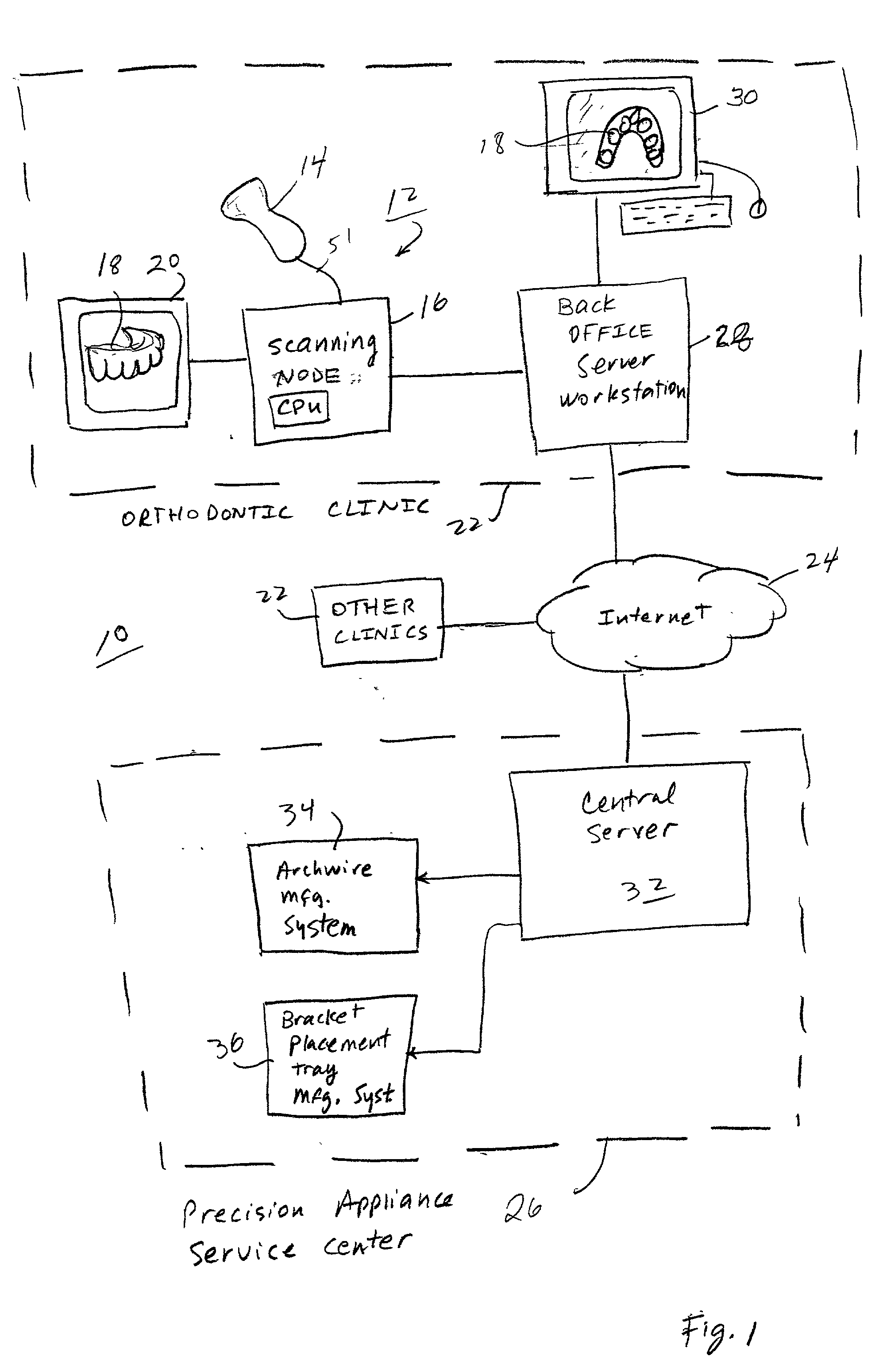
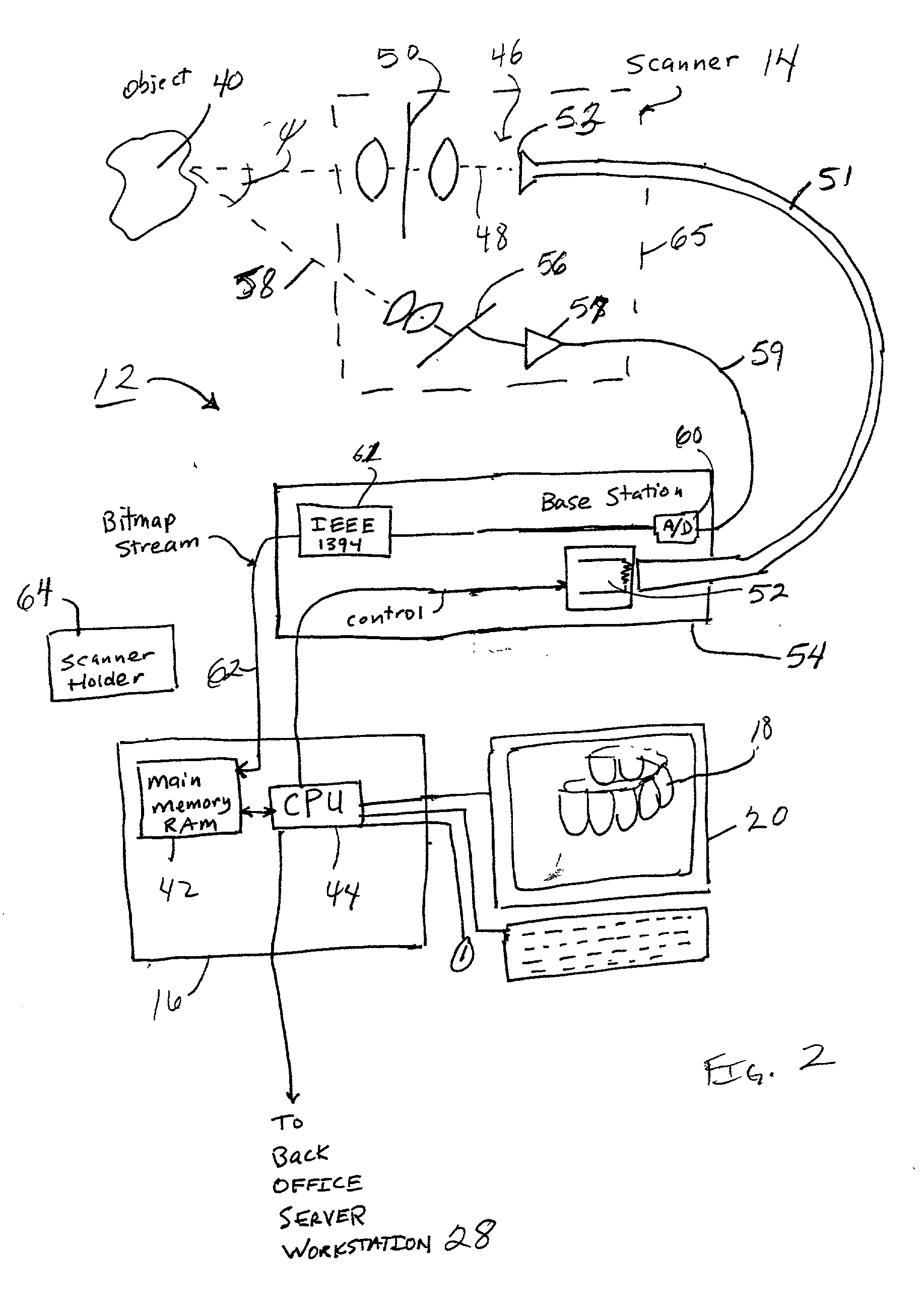
[0091] FIG. 1 is an illustration of an orthodontic care system 10 incorporating a scanner system 12. The scanner system 12 includes a hand-held scanner 14 that is used by the orthodontist or his assistant to acquire three-dimensional information of the dentition and associated anatomical structures of a patient. The images are processed in a scanning node or workstation 16 having a central processing unit, such as a general-purpose computer. The scanning node 16, either alone or in combination with a back-office server 28, generates a three-dimensional computer model 18 of the dentition and provides the orthodontist with a base of information for diagnosis, planning treatment, and monitoring care for the patient. The model 18 is displayed to the user on a monitor 20 connected to the scanning node 16.

[0092] As noted above, the scanner system 12 described in detail herein is optimized for in-vivo scanning of teeth, or alternatively, scanning a plaster model of t...


PUM


Abstract

A method is described for taking a three-dimensional virtual model of the dentition and associated anatomical structures of a patient and isolating individual teeth from the rest of the anatomical structure, e.g. gums, to thereby produce individual, virtual three-dimensional tooth objects. The individual tooth objects can be displayed on the display of an orthodontic workstation and moved independently from each other, and thereby form the basis of planning treatment for the patient. The individual, virtual three-dimensional tooth objects are created by comparing the virtual model of the dentition to virtual, three-dimensional template teeth that are stored in memory in a process described in detail herein. The template teeth can include roots as well as crowns. The template teeth can be stored objects acquired from some external source or alternatively developed from a database of patient scans. Virtual three-dimensional brackets are also stored in the memory of the workstation. The virtual brackets can be placed on the virtual teeth and moved relative to the teeth as needed in a preliminary step in treatment planning.

Description

NOTICE REGARDING COPYRIGHT[0001] A portion of the disclosure of this patent document contains material which is subject to copyright protection. The copyright owner has no objection to the facsimile reproduction by anyone of the patent disclosure, at it appears in the Patent and Trademark Office files or records, but otherwise reserves all copyright rights whatsoever.[0002] A. Field of the Invention[0003] This invention relates generally to the field of orthodontics. More particularly, the invention relates to a computerized method of creating individual, virtual, three-dimensional tooth models from three-dimensional information of a patient's dentition and a template object. The individual tooth models provide the basis for a computerized, interactive, and orthodontist-controlled treatment planning for a patient suffering from a malocclusion.[0004] B. Description of Related Art Orthodontics is a field of medicine concerned with the treatment of a patient suffering from a malocclusi...

Claims


Application Information

Patent Timeline
IPC IPC(8): A61C7/00A61C9/00G06F19/00
CPCA61C7/002A61C9/004G06F19/3437G06F19/3406G06F19/321A61C9/0053G16H40/63G16H50/50B33Y80/00G16H30/40
Inventor RUBBERT, RUDGERWEISE, THOMASSPORBERT, PEERIMGRUND, HANSLEICHNER, MARIOSACHDEVA, ROHIT
Owner ORAMETRIX
Learn More