Method for reading radiation image from stimulable phosphor sheet

a technology of stimulable phosphor and radiation image, which is applied in the direction of material analysis using wave/particle radiation, instruments, conversion screens, etc., can solve the problems of affecting image quality, affecting image quality, and almost impossible to make the surface have no irregularities

Inactive Publication Date: 2002-10-31
FUJIFILM CORP +1
View PDF9 Cites 30 Cited by
  • Summary
  • Abstract
  • Description
  • Claims
  • Application Information

AI Technical Summary

Benefits of technology

[0085] In the formula (II), Ba is preferably included in an amount of half or more of M.sup.II, and Ln is particularly preferably Eu or Ce. The M.sup.IIFX in the formula (II) indicates the crystal structure of BaFX, and it by no means indicates F:X=1:1. The formula (II), therefore, does not indicate resultant stoichiometric composition. It is generally preferred to produce many F.sup.+ (X.sup.-) centers (which are vacant lattice points of X.sup.- ion) in a BaFX crystal, so as to enhance the efficiency of emission stimulated by light in the wavelength region of 600 to 700 nm. In many cases, F is in slight excess of X.
[0091] In the present invention, the phosphor layer can be formed by electron beam-evaporating method, which belongs to the gas phase deposition method. Generally, a phosphor layer formed by the gas phase deposition method comprises only a stimulable phosphor with no binder, and in the phosphor layer there are cracks among the prismatic crystals of the stimulable phosphor. Accordingly, the stimulating light and the stimulated emission are efficiently applied and observed, respectively, and hence a radiation image of high sharpness an be reproduced with high sensitivity. In particular, the electron beam-evaporating method gives regularly aligned prismatic crystals having a good shape. Further, since the vapor source is locally heated and instantly vaporized, the composition of the resultant phosphor in the layer is usually almost the same as that of the phosphor of the vapor source. In contrast, in other gas phase deposition methods, since a component having a high vapor pressure is preferentially vaporized (for example, an activator is vaporized prior to the formation of phosphor matrix), the composition of the resultant phosphor is not coincident with that of the phosphor of the vapor source in many cases.
[0102] On the bottom (reverse) surface of the stimulable phosphor, a rigid support may be provided. It is possible to use the substrate as the support, and in that case the phosphor layer is not peeled from the substrate. Otherwise, after the phosphor layer is peeled from the substrate, the layer may be laminated on another support with an adhesive. The support employed in the invention can be optionally selected from those employed in the conventional stimulable phosphor sheets. It is known that, for improving sensitivity or image quality (sharpness, graininess), a conventional stimulable phosphor-sheet may have a light-reflecting layer containing light-reflecting material such as titanium dioxide and / or a light-absorbing layer containing light-absorbing material such as carbon black. Also in the phosphor sheet of the invention, these layers can be optionally provided according to the purpose and the use of the phosphor sheet. Further, for improving the sharpness of the resultant image, fine hollows or warts may be formed on the phosphor layer-side surface of the support (or on the phosphor layer-side surface of the auxiliary layer such as an undercoating layer (adhesive layer), the light-reflecting layer or the light-absorbing layer, if it is provided).
[0106] It is preferred to provide a protective film on the surface of phosphor layer, so as to ensure treatability of the stimulable phosphor sheet in transportation and to avoid deterioration. In order not to affect the simulating light or the stimulated emission, the film is preferably transparent. Further, for protecting the phosphor sheet from chemical deterioration and physical damage, the film must be chemically stable, high moisture proof and physically strong.
[0112] For enhancing the resistance to stain, a fluororesin layer is preferably provided on the protective film. The fluororesin layer can be form by coating the surface of the protective film with a solution dissolving (or dispersing) a fluororesin in an organic solvent, and drying the applied solution. The fluororesin may be used singly, but in usual a mixture of the fluororesin and a film-forming resin is employed. In the mixture, an oligomer having polysiloxane structure or perfluoroalkyl group can be further added. In the fluororesin layer, fine particle filler may be incorporated so as to reduce blotches caused by interference and to improve the quality of the resultant image. The thickness of the fluororesin layer is generally in the range of 0.5 to 20 .mu.m.
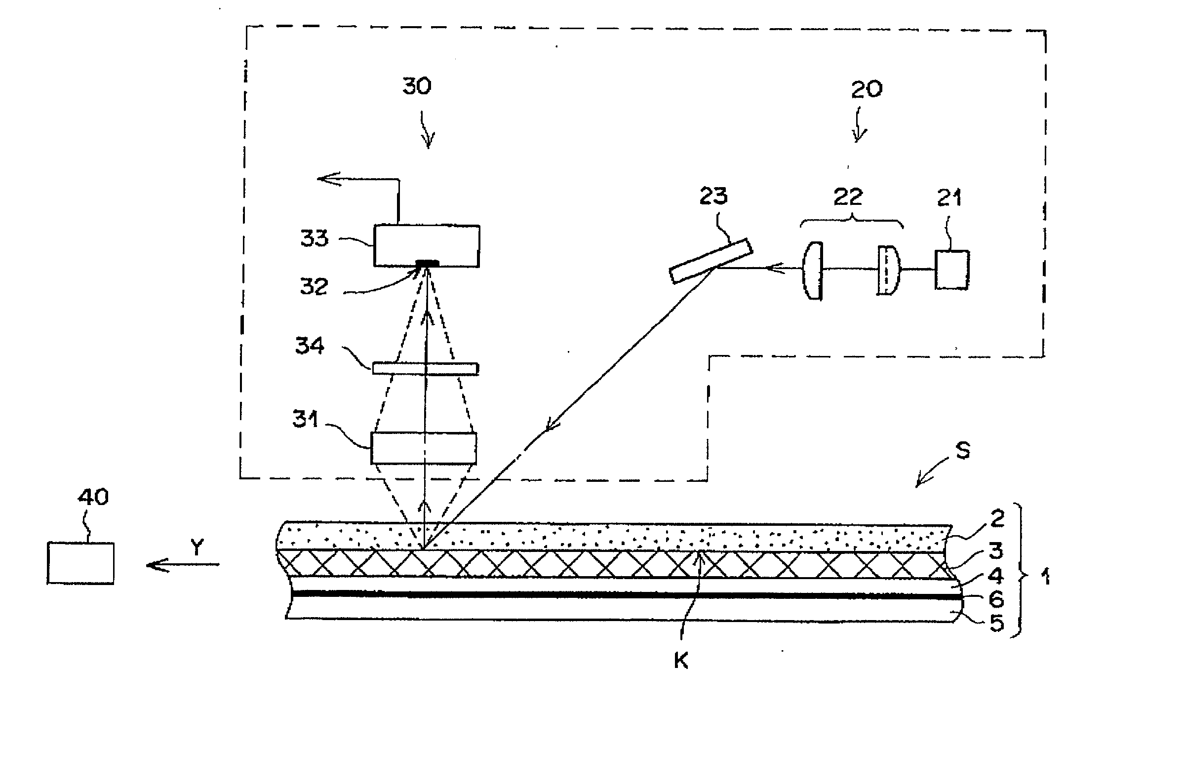
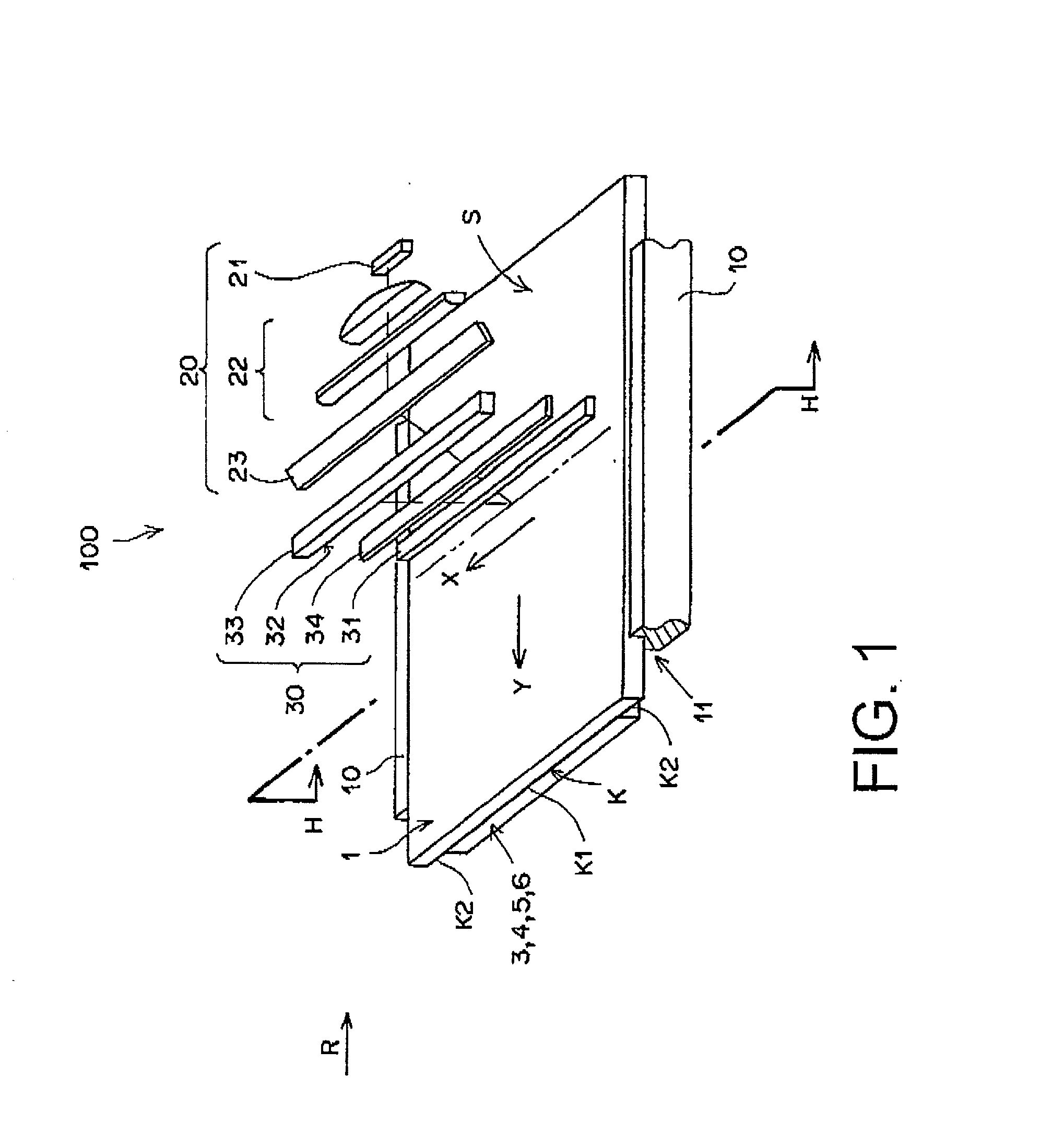
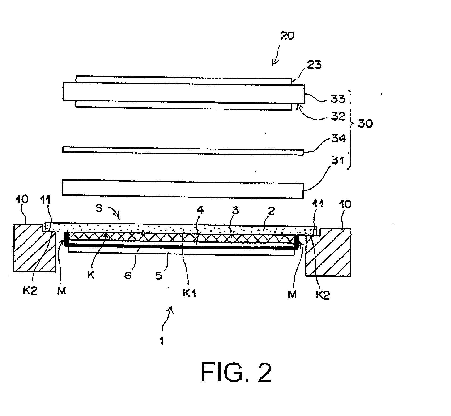
[0137] According to the present invention, the reference plane-indicating means is provided on a stimulable phosphor sheet so that the surface unevenness or irregularity of the phosphor sheet may be within the focal depth of the emission-collecting optical system. Further in the apparatus of the invention, the emission-collecting means reads the image information while moving in contact with the reference plane of the phosphor sheet so that the vertical position of the phosphor sheet can be accurately determined. Therefore, no matter how uneven thickness the phosphor sheet is, variation of the distance between the line sensor and the surface of the phosphor layer can be kept within the focal depth of the emission-collecting optical system. It is also possible to rapidly obtain a radiation image having even image quality (such as sharpness) since the vertical position can be accurately determined. For these reasons, the stimulable phosphor sheet and the radiation image-reading apparatus of the invention are advantageously used particularly in radiography for medical diagnosis, industrial radiography and fluoroscopy.

Problems solved by technology

Consequently, even the slight variation of the distance between the emission-receiving plane and the surface of the stimulable phosphor layer impairs the image quality such as sharpness considerably.
The inventors have further studied the quality of radiation image obtained by the line detection, and found that the surface irregularities of the stimulable phosphor sheet, particularly the surface irregularities of the stimulable phosphor layer impairs the image quality.
The stimulable phosphor layer is formed by, for example, a coating method or a gas phase deposition method, but by any method it is almost impossible to make the surface having no irregularities.
The macroscopic irregularities, however, cause variation of the distance between the emission-receiving plane and the surface of the stimulable phosphor layer, and accordingly sometimes give a radiation image having uneven image quality.
However, it has been found that the distance between the stimulable phosphor layer and the stimulated emission-receiving plane cannot be satisfactory kept at a constant length only by fixing the phosphor sheet onto the stage because the thickness of the stimulable phosphor layer is not strictly the same in the whole area.

Method used


Image

  • Method for reading radiation image from stimulable phosphor sheet
  • Method for reading radiation image from stimulable phosphor sheet
  • Method for reading radiation image from stimulable phosphor sheet

Examples


example 2

[0143] 1) A stimulable phosphor (CsBr:Eu) was deposited on a glass plate (430 mm.times.450 mm, thickness: 0.63 mm) by an electron beam deposition method, to produce a stimulable phosphor sheet composed of the glass plate and a stimulable phosphor layer (410 mm.times.430 mm, thickness: approx. 500 .mu.m) in which prismatic phosphor crystals extending almost vertically from the glass plate were densely aligned.

[0144] 2) Separately, a glass spacer (thickness: 500 .mu.m) was formed on a circumferential area of a glass sheet (rigid protective sheet, 430 mm.times.450 mm, thickness: 8 mm) using a sealing adhesive resin (main component: acrylic resin.

[0145] 3) On the glass spacer was placed via adhesive the stimulable phosphor sheet under the conditions that the phosphor layer was enclosed with the spacer and the glass sheet and the phosphor layer did not become in contact with the glass sheet to produce an optically discontinuous space between the phosphor layer and the glass sheet, as ill...

example 3

[0148] 1) A stimulable phosphor (CsBr:Eu) was deposited on a glass plate (430 mm.times.450 mm, thickness: 8 mm) by an electron beam deposition method, to produce a stimulable phosphor sheet composed of the glass plate and a stimulable phosphor layer (410 mm.times.430 mm, thickness: approx. 500 .mu.m) in which prismatic phosphor crystals extending almost vertically from the glass plate were densely aligned.

[0149] 2) A transparent moisture-proof film (thickness: 60 .mu.m, GL-Au, available from Toppan Printing Co., Ltd.) was placed on the phosphor layer and the glass plate to adhere to the glass plate via adhesive, to form a protective layer, as illustrated in FIG. 16.

[0150] In FIG. 16, the stimulable phosphor sheet is composed of a protective layer 203, a deposited stimulable phosphor layer 201, and a glass plate (rigid plate) 204. The reference plane 202 corresponds to the exposed surface of the glass plate 204. This stimulable phosphor sheet is exposed to X-rays on the side of the u...

example 4

[0152] 1) A stimulable phosphor (CsBr:Eu) was deposited on a glass plate (rigid plate, 430 mm.times.450 mm, thickness: 8 mm) by an electron beam deposition method, to produce a stimulable phosphor sheet composed of the glass plate and a stimulable phosphor layer (410 mm.times.430 mm, thickness: approx. 500 .mu.m) in which prismatic phosphor crystals extending almost vertically from the glass plate were densely aligned.

[0153] 2) Separately, a glass spacer (thickness: 500 .mu.m) was formed on a circumferential area of a glass sheet (protective sheet, 430 mm.times.450 mm, thickness: 0.7 mm) using a sealing adhesive resin (main component: acrylic resin).

[0154] 3) on the glass spacer was placed via adhesive the stimulable phosphor sheet under the conditions that the phosphor layer was enclosed with the spacer and the glass sheet and the phosphor layer did not became in contact with the glass sheet to produce an optically discontinuous space between the phosphor layer and the glass sheet,...


PUM


Abstract

A method for reading a radiation image from a stimulable phosphor sheet composed of a substrate and a stimulable phosphor layer containing a latent radiation image by as of a radiation image-reading means having a stimulating light-applying unit and a stimulated emission-collecting unit having a lens and a stimulated emission-receiving plane, which is performed by the steps of applying a stimulating light onto the phosphor layer under the condition that the phosphor sheet moves along its sheet plane in relation to the stimulated emission-collecting unit; collecting a stimulated emission emitting from the area onto which the stimulating light is applied on the emission-receiving plane through the lens; and photoelectrically converting the collected emission into electric signals in the stimulated emission-collecting unit, is improved by moving the stimulable phosphor sheet in relation to the emission-collecting unit under the condition that the stimulating light-applied area of the stimulable phosphor layer is kept apart from the center of the emission-receiving plane with a space in the range defined by a combination of a reference space and a focal depth of the lens, in which the reference space is defined by a length at which the stimulated emission emitting from the phosphor layer focuses on the emission-receiving plane after passing through the lens.

Description

[0001] The present invention relates to a method for reading radiation image from a stimulable phosphor sheet in which a latent radiation image is contained, and an apparatus for the radiation image reading method.[0002] When a stimulable phosphor is exposed to a radiation such as X-ray, it absorbs and stores a portion of energy of the radiation. The stimulable phosphor then emits stimulated emission according to the level of the stored energy when the phosphor is exposed to stimulating light.[0003] A radiation image recording and reproducing method utilizing the stimulable phosphor has been widely employed in practice. This method utilizes a stimulable phosphor sheet (also called, radiation image storage panel), and comprises the steps of causing the stimulable phosphor of the phosphor sheet to absorb radiation energy having passed through an object or having radiated from an object; sequentially exciting the stimulable phosphor with a stimulating light such as a laser beam to emit...

Claims


Application Information

Patent Timeline
IPC IPC(8): G03B42/08
CPCG03B42/08
Inventor NERIISHI, KEIKOHOSOI, YUICHI
Owner FUJIFILM CORP
Why Eureka
Try Eureka