Motor

a technology of motors and bearing devices, applied in the direction of mechanical energy handling, mechanical apparatus, rigid support of bearing devices, etc., can solve the problems of different thermal expansion of bearing devices, shortening the service life of bearing devices, and generating vibration

Inactive Publication Date: 2002-09-12
MINEBEA CO LTD
View PDF4 Cites 9 Cited by
  • Summary
  • Abstract
  • Description
  • Claims
  • Application Information

AI Technical Summary

Benefits of technology

0019] The bearing device may include low expansion rings press fit around the outer periphery of the outer ring, wherein the low expansion rings are made of a material lower in its coefficient of linear expansion than that employed for the outer ring. The balls are preferably of ceramic material, and the low expansion members are preferably also of ceramic material.

Problems solved by technology

However, upon rising the temperature of the bearing device under the effect of the frictional heat generated by the rotation or the operation of the bearing device itself or the effect of heat energy supplied from the outside of the bearing device, the thermal expansion of the components of the bearing device will be caused differently.
This will lead to the shortening of the service life of the bearing device.
Further, the enlargement of the radial clearance will generate the vibration upon rotation and the noise caused thereby.
This also deteriorates the precision or the quietness of the rotation of the motor, and in some cases, this will bring the reduction of the reliability of the equipment such as the hard disc drive means to which the bearing device is to be incorporated.
In such a case, the before mentioned problem caused by the difference of the amount of thermal expansion between components will become serious, since the amount of thermal expansion of the ceramic material is further lower (about {fraction (1 / 10)}) than that of the steel material used for the inner and outer rings.

Method used


Image

  • Motor
  • Motor
  • Motor

Examples


first embodiment

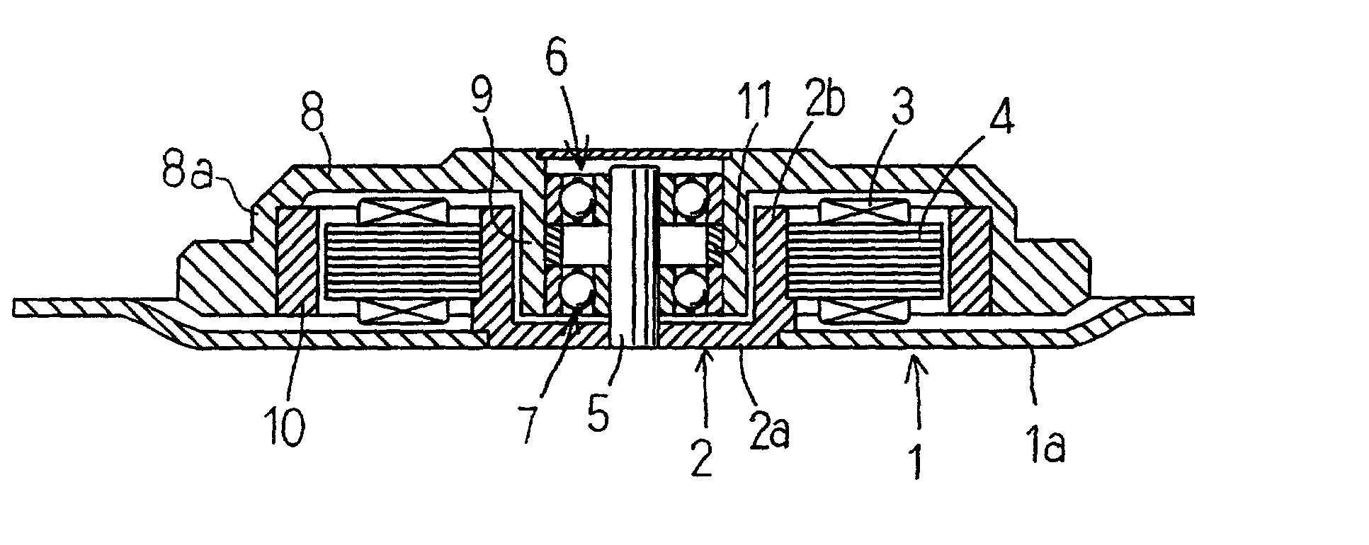
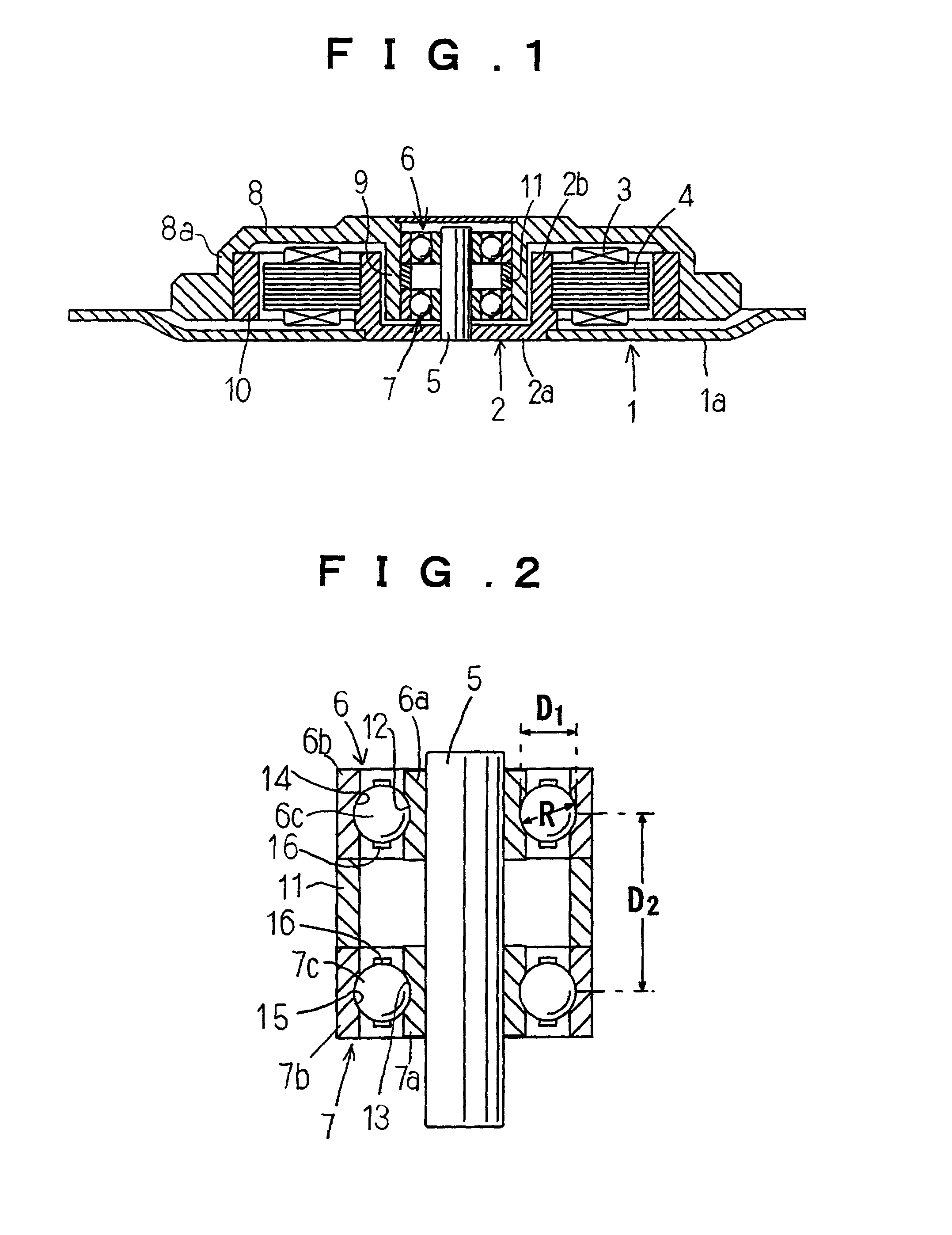
[0031] A motor in accordance with the present invention includes as shown in FIG. 1, a base member 1 including a flange 1a and a stator yoke holder 2 attached to the central portion of the flange. The stator yoke holder 2 includes a bottom plate 2a and a cylindrical rib 2b formed integrally around the outer periphery of the bottom plate with the same material as that of the bottom plate. The cylindrical rib 2b is provided around the outer periphery thereof with stator yokes 4 around which coils 3 for energizing the motor are wound.

[0032] A shaft 5 is stationary secured on the central portion of the bottom plate 2a of the stator yoke holder 2 to extend upwardly therefrom. A rotor 8 including a sleeve 9 formed integrally therewith by employing the same material as that of the rotor is fit around the outer periphery of the upper and lower ball bearing 6, 7 mounted around the shaft 5. The rotor 8 or the rotational member of the motor can thus be supported rotatably through the bearings ...

second embodiment

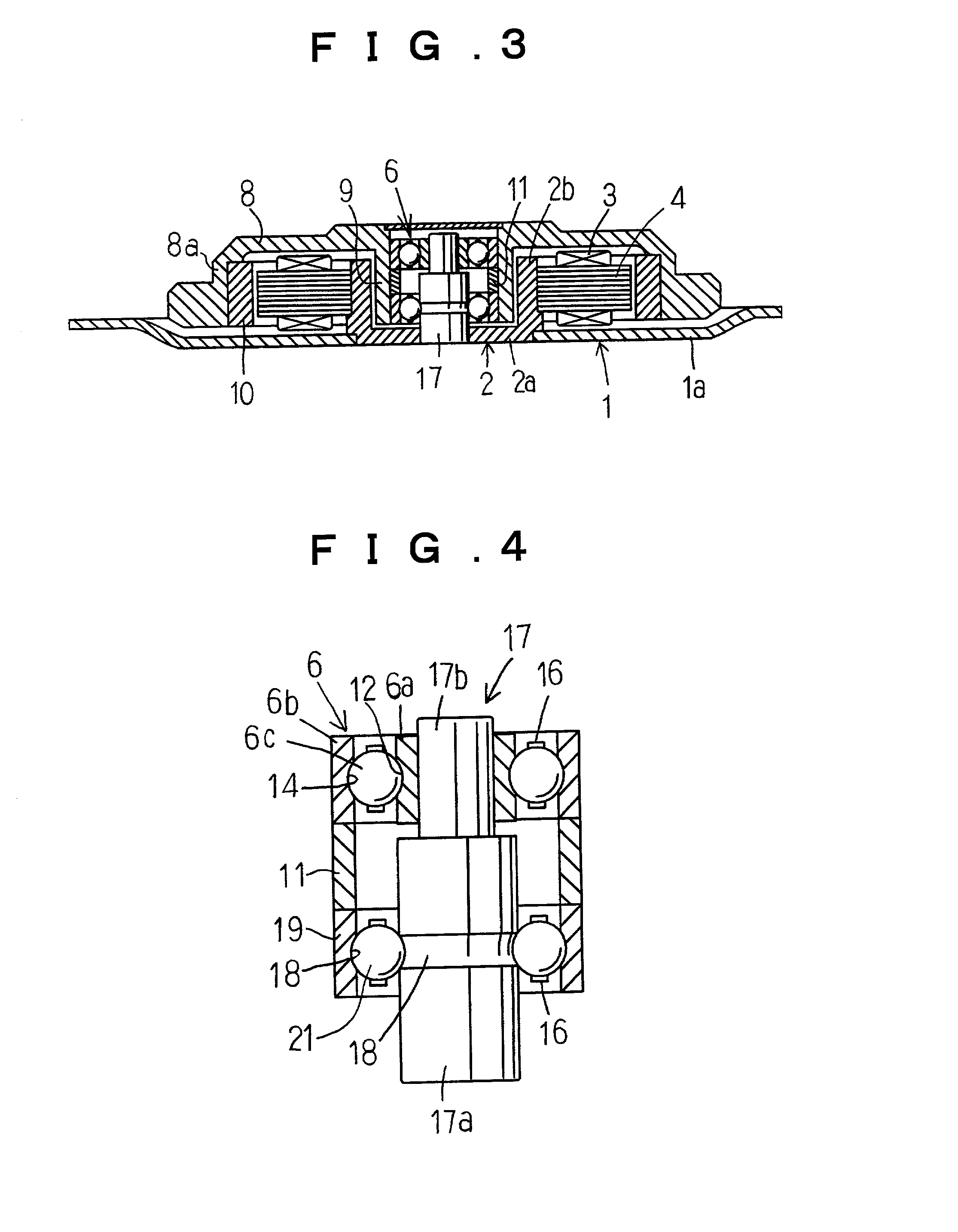
[0043] The bearing device of the motor of the second embodiment in accordance with the present invention comprises as shown in FIGS. 3, 4, a stepped shaft 17 including a larger diameter shaft portion 17a and a reduced diameter shaft portion 17b, and an inner ring 6a of the ball bearing 6 fit around the reduced diameter shaft portion 17b of the stepped shaft. The larger diameter shaft portion 17a includes an inner ring raceway 18 formed directly around the outer periphery thereof.

[0044] The lower outer ring 19 is provided around the larger diameter shaft portion 17a, and a plurality of balls 21 of steel or ceramic material for the lower row are disposed between the lower outer ring raceway 20 formed on the inner peripheral surface of the outer ring 19 and the lower inner ring raceway 18.

[0045] The bearing device of the motor of the second embodiment in accordance with the present invention is also provided with the spacer 11 formed for example of aluminum or synthetic resin larger in...

third embodiment

[0051] The bearing device of the motor of the third embodiment as shown in FIGS. 5, 6 can be differentiated from that of the first one as shown in FIGS. 1, 2 in that the low expansion rings 22, 22 are press fit around the outer periphery of the upper and lower outer rings 6b, 7b of the bearing device to inhibit the expansion of the outer rings 6b, 7b in radial direction in order to suppress the amount of expansion of the outer ring raceways 14, 15. The coefficient of expansion of the low expansion rings is lower than that of the outer rings 6b, 7b.

[0052] In other words, the amount of expansion of the inner diameter of the outer ring raceway to the amount substantially equal to the amount of expansion of the outer diameter of the inner ring raceway to keep the spacing between both rolling contact grooves substantially constant by setting the pressure to be applied on the outer ring through said low expansion ring 22 in an appropriate value. Thus the radial spacing can be maintained i...


PUM


Abstract

A motor of long life and high precision in its rotation wherein the variation on the rotation and the noises generated thereby are suppressed by maintaining the radial clearance between the components of the bearing device constantly in an appropriate value even if the thermal expansion of the components is caused by rising the temperature thereof. A motor having a rotational member supported rotatably through a bearing device provided on a base member of the motor, said bearing device comprising upper and lower ball bearings each of which includes an inner ring fit around a shaft of the motor, an outer ring, and a plurality of balls interposed therebetween, said bearing device further comprising a spacer interposed between the outer rings of the upper and lower ball bearings wherein the spacer is made of material larger in its coefficient of linear expansion than that of the upper and lower outer rings.

Description

[0001] 1. Technical Field[0002] The present invention relates to a motor suitable for office automation equipment such as hard disc drive devices of computers.[0003] 2. Description of the Prior Art[0004] The motor for driving the magnetic disc or discs of the hard disc drive devices of computers may have for example the structure in which a pair of single row bearing device or ball bearings are used in parallel with each other. In such an structure, the shaft stationary secured on the base member to extend therefrom is provided with a pair of upper and lower ball bearings and a rotor 45 or the rotational member for mounting the magnetic disc or discs is fit over the outer periphery of the ball bearings.[0005] Between inner and outer ring raceways and balls interposed therebetween, there is a radial clearance which is a total of a movement between the outer ring and the inner ring wherein the inner ring is stationary secured and the outer ring is displaced in the radial direction.[00...

Claims


Application Information

Patent Timeline
Patent Type & Authority Applications(United States)
IPC IPC(8): H02K5/173F16C19/52F16C33/58F16C35/06F16C19/54F16C25/08F16C35/077
CPCF16C19/54F16C35/077H02K5/1737F16C19/525F16C35/067F16C2370/12F16C19/06F16C2202/22
Inventor OBARA, RIKURO
Owner MINEBEA CO LTD
Why Eureka
Try Eureka