Saw blade for hand-held tools

Inactive Publication Date: 2002-09-05
ROBERT BOSCH GMBH
View PDF16 Cites 43 Cited by
  • Summary
  • Abstract
  • Description
  • Claims
  • Application Information

AI Technical Summary

Benefits of technology

[0003] The saw blade of the invention has the advantage that by the partial reduction of individual saw teeth, or pairs or groups of saw teeth, a very good blade life and service life of the saw blade are attained despite a thick, stable saw blade. The cutting forces are optimized, and the heat production at the saw blade during sawing is reduced.[0004] By the provisions recited in the other claims, advantageous refinements of and improvements to the saw blade defined by claim 1 are possible.[0005] In one advantageous embodiment of the invention, the tooth width of the saw teeth in one set of portions of the toothing is equivalent to the thickness of the blade back, and the tooth width differing from it of the saw teeth in the other portions of the toothing is brought about by material removal or material compacting, such as swaging. To that end, recesses spaced apart from one another are made in the blade back on both sides of the blade back and extend past the saw teeth as far as the underside, remote from the blade back, of the teeth, and the recesses on one side of the blade back and the recesses on the other side of the blade back are disposed offset from one another longitudinally of the saw blade.[0006] In alternative embodiments of the invention, the recesses are extended as far as the upper edge, remote from the teeth, of the blade back, or they end at a distance in front of this upper edge.[0007] In an advantageous embodiment of the invention, the recesses are inclined relative to the teeth at an acute angle in the advancement direction of the saw blade, and preferably the acute angle is equivalent to the rake angle of the saw teeth. Because of the oblique edges of the channels formed by the recesses, an additional advancement force against the workpiece ensues, because of the frictional forces.

Problems solved by technology

For rough, heavy-duty use, stable saw blades up to 1.6 mm thick are used, but with increasing saw blade thickness the blade life and the service life of the saw blades decrease.

Method used


Image

  • Saw blade for hand-held tools
  • Saw blade for hand-held tools
  • Saw blade for hand-held tools

Examples


Embodiment Construction

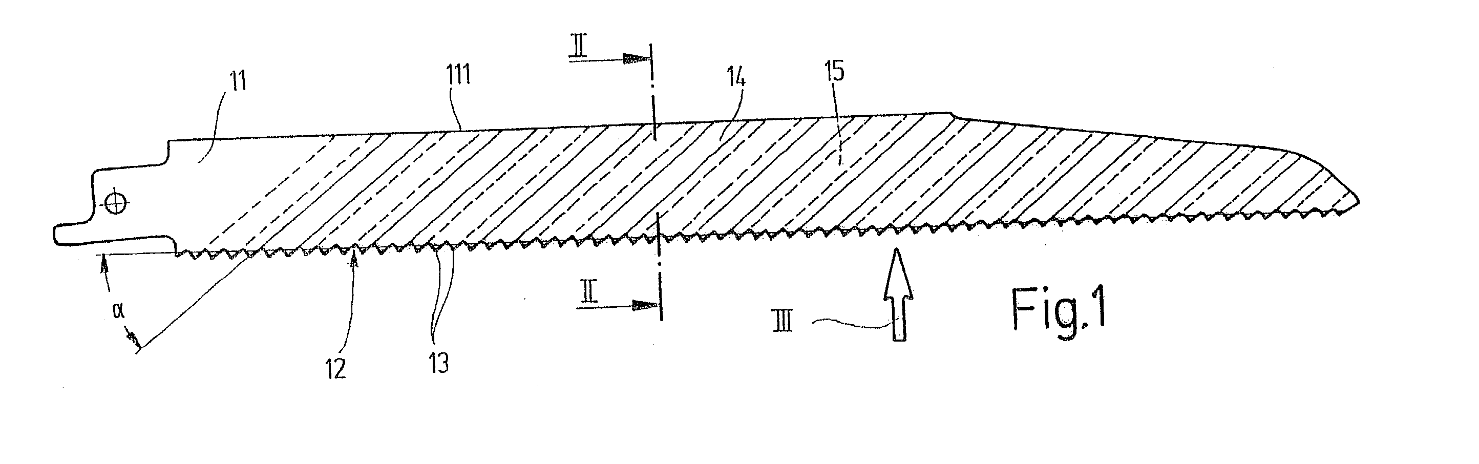
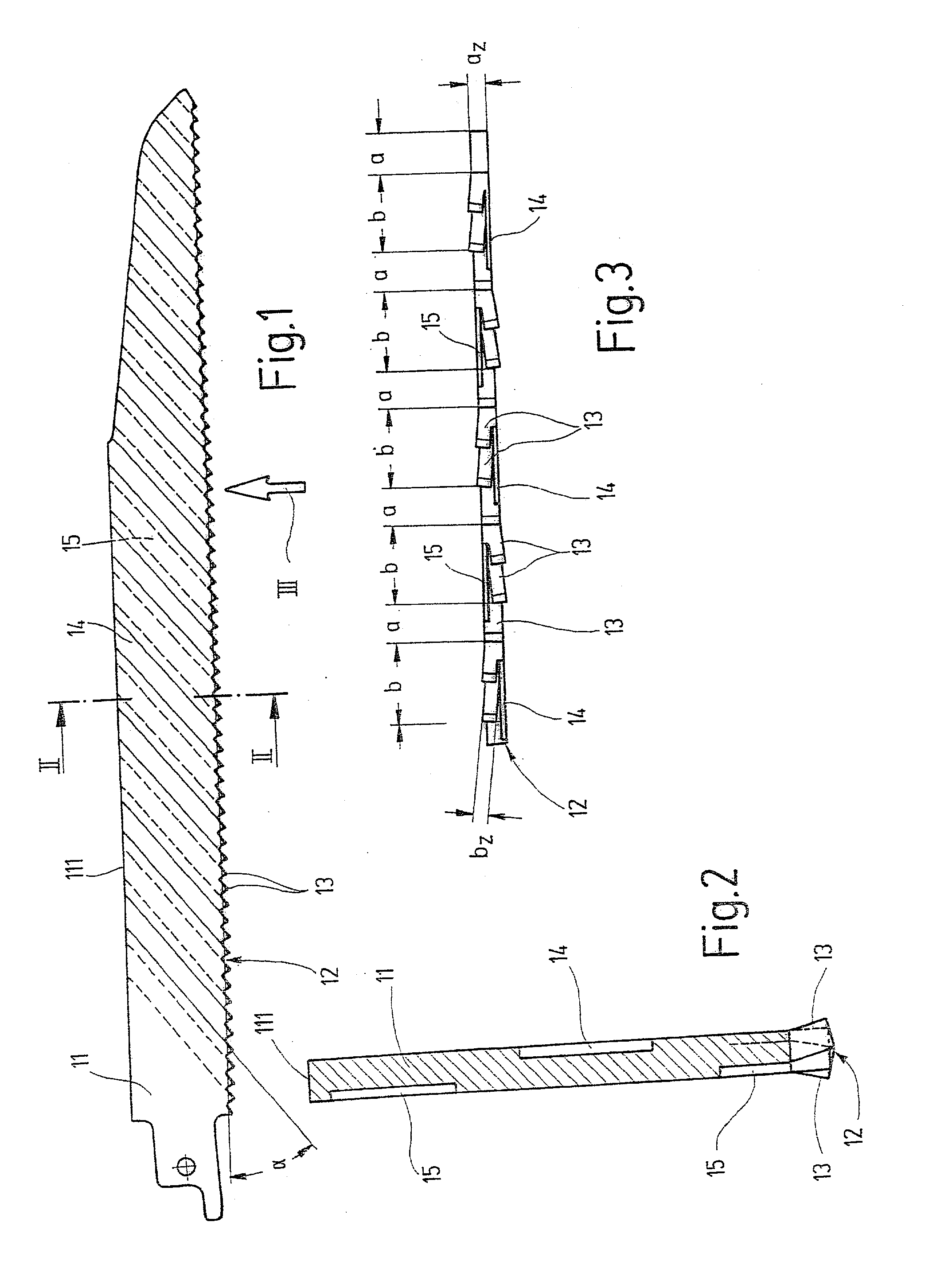
[0016] The saw blade for a power reciprocating saw (saber saw, piercing saw or the like) shown in side view in FIG. 1, as an exemplary embodiment for a power tool in general, has a blade back 11 and a toothing 12, extending along the lower edge of the blade back and comprising many saw teeth 13 lined up in succession. In successive portions a and b (FIG. 3) of the toothing 12, each with an integral number of saw teeth 13, the saw teeth 13 are embodied with the same tooth width a.sub.z or b.sub.z, which however differs from that of the saw teeth 13 in the preceding or succeeding portion b or a, respectively. In the exemplary embodiment of FIGS. 1-3, the portions a of the toothing 12 each include one saw tooth, while the portions b of the toothing 12 each include two saw teeth 13. The tooth width a.sub.z of the saw teeth 13 in the portions a is equivalent to the thickness of the blade back 11, while the tooth width b.sub.z of the saw teeth 13 in the portions b by comparison is smaller...


PUM

PropertyMeasurementUnit
Angleaaaaaaaaaa
Widthaaaaaaaaaa

Abstract

In a saw blade for power tools, in particular for power reciprocating saws, with a blade back (11) and a toothing (12) extending along the lower edge of the blade back and comprising many saw teeth (13) lined up in succession, in order to increase the blade life and service life of the saw blade, especially in a thick, stable embodiment, the saw teeth (13) in successive portions (a, b) of the toothing (12) are embodied with the same tooth width (az, bz), which however differs from that of the saw teeth (13) in the preceding or the succeeding portion (b, a) of the toothing (12).

Description

PRIOR ART[0001] The invention relates to a saw blade for power tools, in particular for power reciprocating saws, such as saber or piercing saws, of the type defined by the preamble to claim 1.[0002] Known saw blades of this type have the same tooth width over the length of the teeth, and this tooth width is dictated by the thickness of the saw blade. For free-cutting of the saw blade, the saw teeth are transposed in the workpiece, so that the tooth tips protrude laterally slightly past the contour of the blade back in alternation. For rough, heavy-duty use, stable saw blades up to 1.6 mm thick are used, but with increasing saw blade thickness the blade life and the service life of the saw blades decrease.ADVANTAGES OF THE INVENTION[0003] The saw blade of the invention has the advantage that by the partial reduction of individual saw teeth, or pairs or groups of saw teeth, a very good blade life and service life of the saw blade are attained despite a thick, stable saw blade. The cu...

Claims


Application Information

Patent Timeline
IPC IPC(8): B23D61/12B27B33/10B23D65/00
CPCB23D61/121B23D61/123B23D65/00Y10T83/9346Y10T83/9319Y10T83/935
Inventor KOCHER, MARTINGROLIMUND, DANIEL
Owner ROBERT BOSCH GMBH
Why Eureka
Try Eureka