
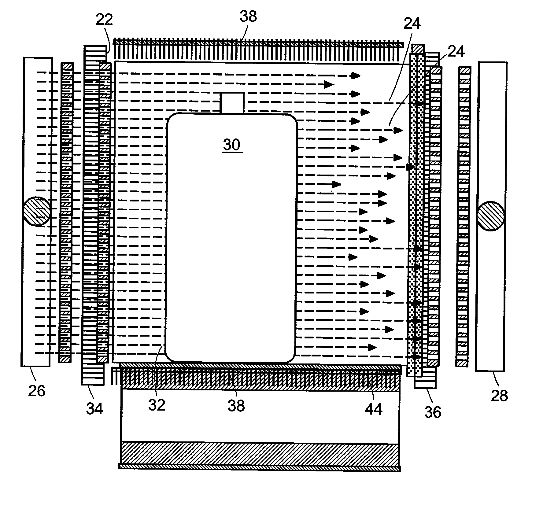
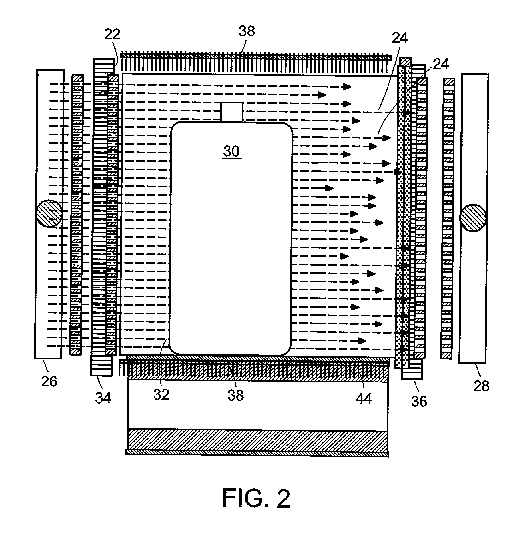
System for inspecting the contents of a container

a container and container technology, applied in the field of system inspection, can solve the problems of heavy and slow current methods of providing beams that either scan periodically or may be directed to a specified direction, limited areas that may be scanned at a given time, and heavy weight of current x-ray steering devices

Inactive Publication Date: 2002-07-25
SILICON VALLEY BANK
View PDF0 Cites 56 Cited by
  • Summary
  • Abstract
  • Description
  • Claims
  • Application Information

AI Technical Summary

Problems solved by technology

Methods currently employed for providing a beam that either scans periodically or may be directed to a specified direction are typically massive and slow.
Consequently, the areas that may be scanned at a given time are limited by how fast the device which steers the x-ray beam can be moved.
Further, lead is usually used to absorb any radiation that is undesirable, which makes current x-ray steering devices heavy and awkward.
Additionally, with fixed electron beam sources, x-ray imaging may be distorted.

Method used


Image

  • System for inspecting the contents of a container
  • System for inspecting the contents of a container
  • System for inspecting the contents of a container

Examples


Embodiment Construction

[0027] FIG. 1(a) shows a plan view of a preferred embodiment of an apparatus for generating sequential beams of penetrating electromagnetic radiation, designated generally by numeral 10. A source 12 supplies a beam of charged particles 14 that are accelerated to a surface of a target 16. The beam 14 can either be scanned across the target 16 in a fixed pattern or directed to successive locations in a particular pattern on the target. A region 20 of the target 16, shown more clearly in FIG. 7, impinged upon by the charged particle beam 14 shall be referred to as the "focal spot size." Electromagnetic beam director 18 can be any electromagnetic beam directing arrangement such as magnetic or electrostatic yokes. Penetrating electromagnetic radiation is emitted by target 16. Penetrating electromagnetic radiation refers to electromagnetic waves of sufficient energy to pass through articles to be inspected, and may be referred to herein, without limitation, as x-rays. The x-rays pass thro...


PUM

PropertyMeasurementUnit
ninety degree angleaaaaaaaaaa
distanceaaaaaaaaaa
angleaaaaaaaaaa

Abstract

An apparatus and method for generating electronically steerable beams of sequential penetrating radiation. Charged particles from a source are formed into a beam and accelerated to a target. Electromagnetic radiation generated by the target is emitted with an angular distribution which is a function of the target thickness and the energy of the particles. A beam of particles is produced by allowing the radiation to exit from an apparatus through a collimator proximal to the target. The direction of the beam is determined by the point of radiation production and the corresponding array of transmission regions of the collimator.

Description

[0001] This application is a Continuation-in-Part of co-pending application No. 09 / 395,331 filed Sep. 13, 1999, claiming priority from provisional application 60 / 110,525 filed Dec. 1, 1998, and furthermore claims priority from provisional application No. 60 / 140,767, filed Jun. 24, 1999. All of these applications are incorporated herein by reference.[0002] The present invention relates to the production of sequential beams of penetrating electromagnetic radiation and, in particular, to the generation of sequential and parallel beams of radiation in the x-ray region of the electromagnetic wave spectrum.BACKGROUND TO THE INVENTION[0003] For many applications of x-ray radiation, steerability of the x-ray illumination is advantageous. Methods currently employed for providing a beam that either scans periodically or may be directed to a specified direction are typically massive and slow. This is because current methods attempt to steer the x-ray radiation either by moving the source in it...

Claims


Application Information

Patent Timeline
Patent Type & Authority Applications(United States)
IPC IPC(8): G01N23/20G01V5/00
CPCG01N23/20G01V5/0016G21K1/025H01J35/14H01J35/30H01J35/153
Inventor GRODZINS, LEE
Owner SILICON VALLEY BANK
Learn More