Fiber optic image mapping apparatus and method

a fiber optic and image mapping technology, applied in the field of fiber optic image mapping apparatus and method, can solve the problems of not fully focused image in a single plane, does not disclose, teach, or suggest reshaping the image, and other portions are blurred

Inactive Publication Date: 2002-07-25
CYCLOVISION TECH
View PDF4 Cites 22 Cited by
  • Summary
  • Abstract
  • Description
  • Claims
  • Application Information

AI Technical Summary

Benefits of technology

0031] There has thus been outlined, rather broadly, the more important features of the invention in order that the detailed description thereof that follows may be better understood, and in order that the prese

Problems solved by technology

He does not disclose, teach, or suggest reshaping the image to fit a sensor surface by varying the cross-sectional shape of a fiber bundle.
However, since the mirror is curved, the image is not entirely focused in a single plane.
Consequently, when some portions of the image are focused on the plane of the sensor, other portions are blurred.

Method used


Image

  • Fiber optic image mapping apparatus and method
  • Fiber optic image mapping apparatus and method
  • Fiber optic image mapping apparatus and method

Examples


Embodiment Construction

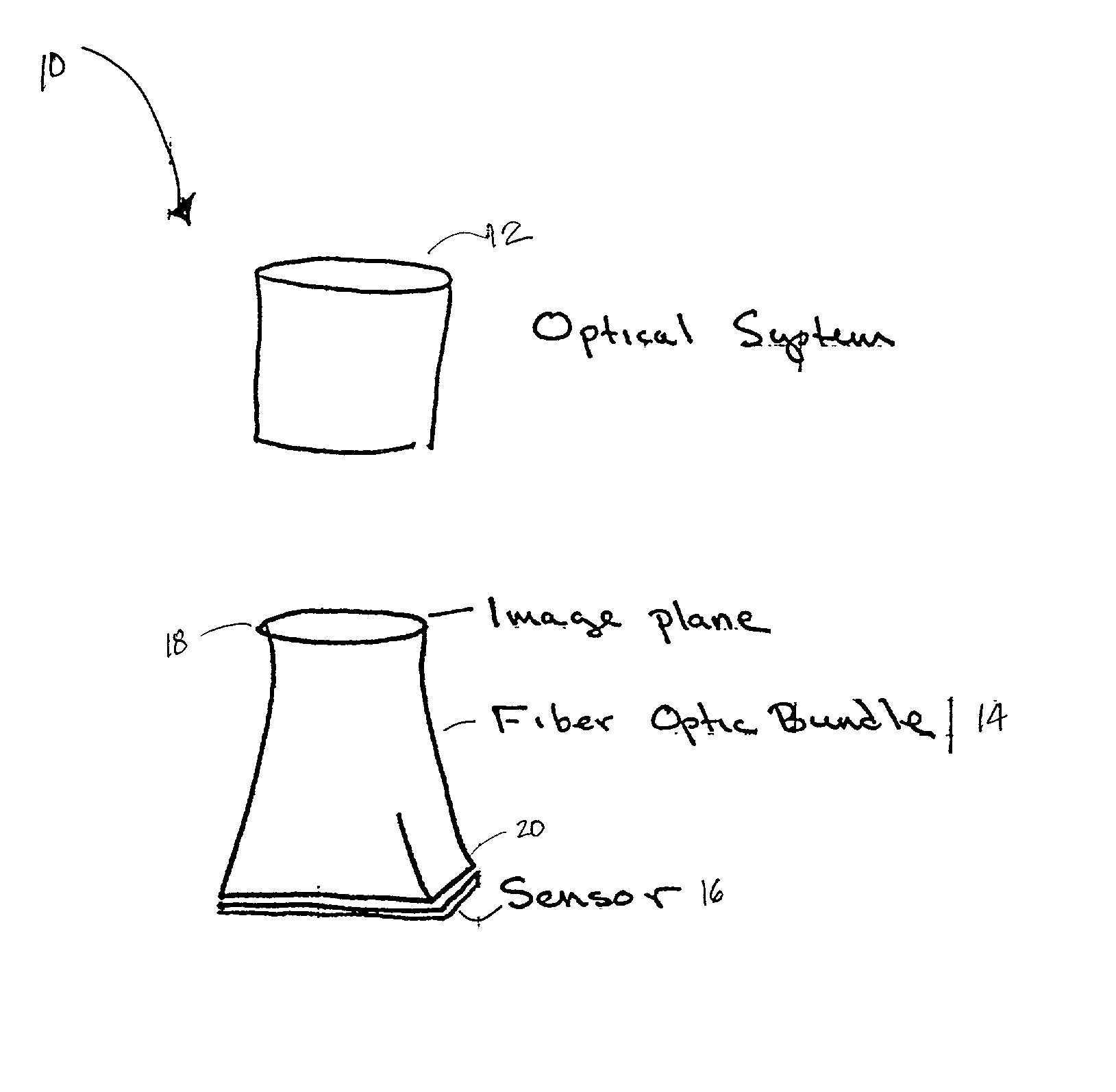
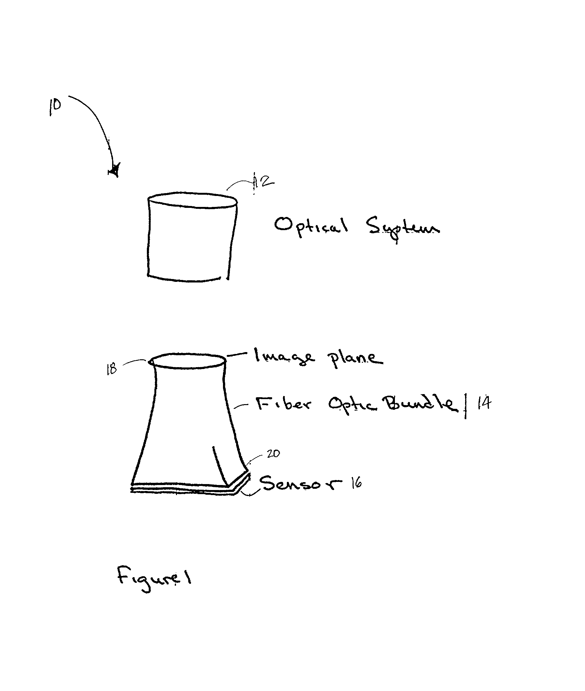
[0034] FIG. 1 illustrates an apparatus for transforming the shape of an image, in accordance with a preferred embodiment.

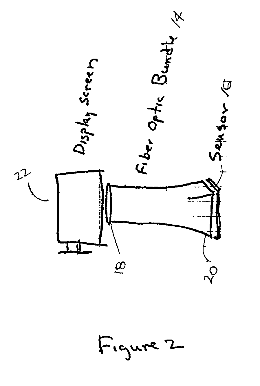
[0035] FIG. 2 illustrates the present invention employed with a mapping device, such as a display tube.

[0036] FIG. 3 illustrates a cross-sectional view of an apparatus for eliminating blurring according to another aspect of the present invention.

[0037] FIG. 4 illustrates a perspective view of an apparatus for eliminating blurring according to another aspect of the present invention.

DESCRIPTION OF PREFERRED EMBODIMENTS

[0038] One embodiment of the present invention is shown in FIG. 1, which is an apparatus for transforming the shape of an image. The apparatus 10 comprises an optical system 12, a fiber optic bundle 14, and a sensor 16, such as a planar charged-coupled device (CCD) sensor. Preferably, the optical system 12 may be an omni-directional imaging system. Alternatively, the optical system may comprise one or more lens or mirrors. Also, the sensor, which may ...


PUM


Abstract

An apparatus for transforming the shape of an image in a way that utilizes substantially all the available pixels for both the image generated and the sensor to which the image is projected, is disclosed. Also disclosed is an apparatus and method to reduce or eliminate substantially any blurring associated with a non-planar focal plane associated with an image generated from a curved mirror, particularly when some portions of the image are focused on the plane of the sensor and other portions are blurred. Loss of image resolution is eliminated, thereby achieving desired fiber optic image mapping, by the present invention for coherent and incoherent fiber optic cables.

Description

PRIORITY[0001] The present application claims priority to the provisional patent application Serial No. 60 / 171,306 entitled, "Fiber Optic Image Mapping Apparatus and Method", filed Dec. 21, 1999.[0002] The present invention generally relates to electrical output optical sensors. More particularly, the present invention relates to optical fiber cables for conveying information to such sensors.BACKGROUND OF INVENTION[0003] In many imaging applications, including omni-directional imaging, an image is obtained through an optical system comprising lenses and / or mirrors, and then projected onto a sensor, typically a planar charged-coupled device ("CCD") image sensor or a CMOS image sensor.[0004] Generally, the shape of the image is very different than that of the CCD sensor. CCDs and similar sensors, for example, are typically rectangular, with an aspect ratio of 4 to 3. New sensors for digital high definition television (HDTV) may have an aspect ratio of 16 to 9.[0005] In omni-directiona...

Claims


Application Information

Patent Timeline
IPC IPC(8): G02B6/04G02B6/06G02B6/08H04N1/195H04N5/225
CPCG02B6/04G02B6/06G02B6/08H04N1/195H04N1/19589H04N5/2254
Inventor KOREIN, JAMES
Owner CYCLOVISION TECH
Why Eureka
Try Eureka