
Device for printing on paper tape and for cutting the tape into printed tickets

a technology of paper tape and cutting tape, which is applied in the direction of printing, shearing apparatus, other printing apparatus, etc., can solve the problems of difficult to engage the leader end of the tape, the opening motor-driven cutter device is complex mechanically and subject to frequent breakdown, and the random operation of the static cutter device, etc., to achieve the effect of simplifying the access

Inactive Publication Date: 2002-06-13
AXIOHM
View PDF0 Cites 11 Cited by
  • Summary
  • Abstract
  • Description
  • Claims
  • Application Information

AI Technical Summary

Benefits of technology

[0008] The present invention provides a remedy to the drawbacks of all known devices by using a printer structure which opens and a cutter device structure-which does not open but which has simplified access.
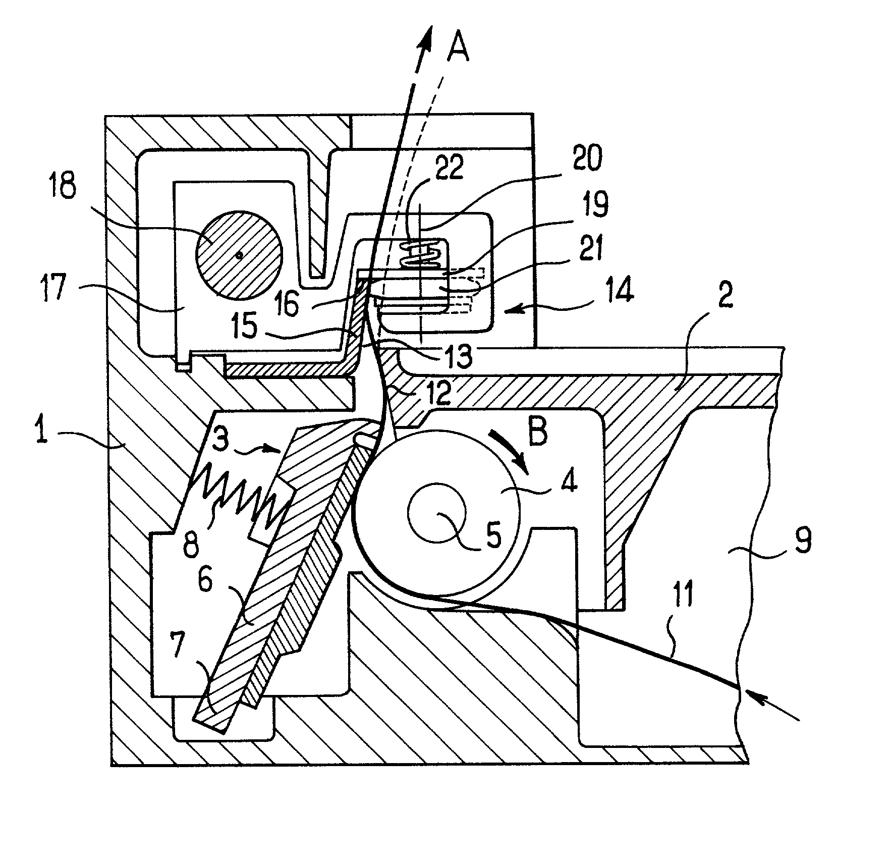
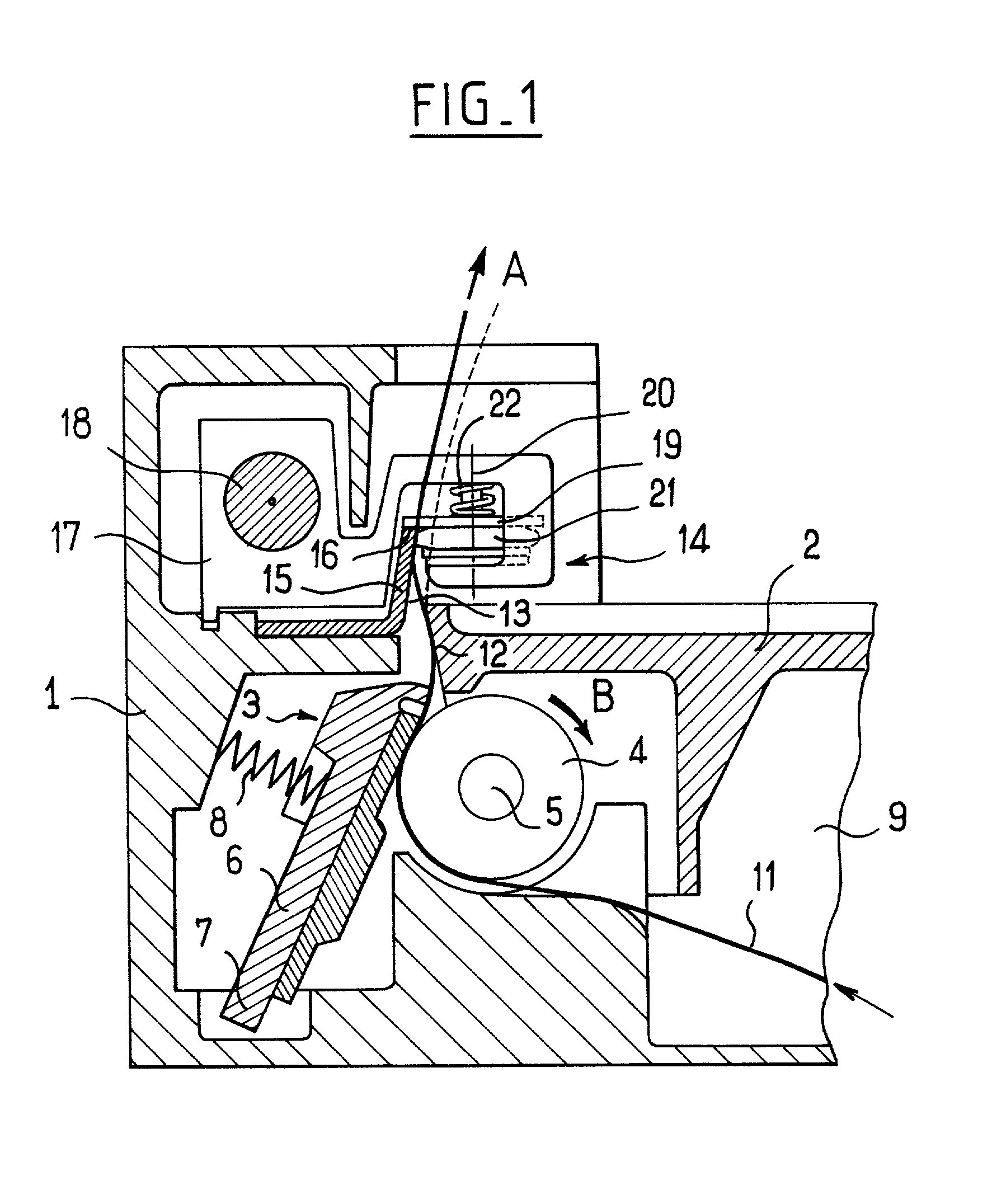
[0010] This S-bend confers stiffness to the portion of tape that facilitates the cutting operation since the tape is then better at withstanding the lateral drive forces to which it is subjected while the knife passes along the edge of the fixed blade.
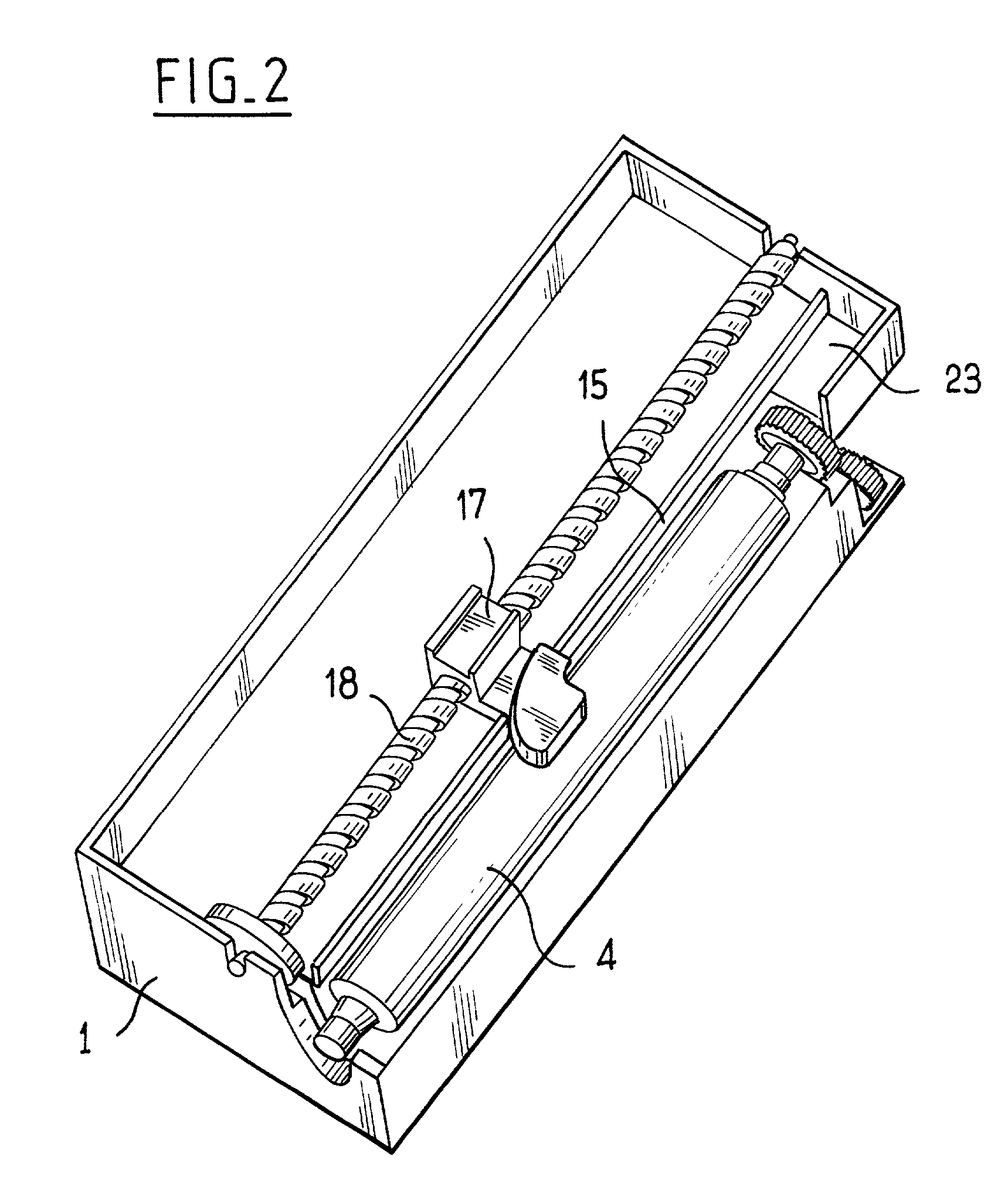
[0016] The carriage is thus easily displaced using a motor to drive the wormscrew.

Problems solved by technology

Static cutter devices are subject to random operation because of intervention by the user who exerts traction more or less correctly for detaching the ticket.
Opening motor-driven cutter devices are complex mechanically and subject to frequent breakdowns because of the play which exists between the two blades specifically because they can be separated.
Finally, non-opening cutter devices generally include paper guide means upstream from the cutter blades which form a tunnel making it awkward to engage the leader end of the tape each time the roll is changed.

Method used


Image

  • Device for printing on paper tape and for cutting the tape into printed tickets
  • Device for printing on paper tape and for cutting the tape into printed tickets
  • Device for printing on paper tape and for cutting the tape into printed tickets

Examples


Embodiment Construction

[0020] With reference to the figures, a printer device of the invention comprises a fixed frame 1 having a moving frame portion hinged thereto to form a cover 2. The cover 2 closes a compartment 9 for receiving a roll of paper tape 11.

[0021] The device of the invention is fitted with a printer given overall reference 3, comprising a paper drive roller 4, said roller being mounted to rotate about an axis 5 relative to the cover 2. When the cover 2 is in the closed position, the drive roller 4 co-operates with a thermal print head 6 mounted on the fixed frame 1 to pivot about an axis 7 against a spring 8 bearing against the fixed frame 1 and causing the print head 6 to be pressed against the drive roller 4.

[0022] The paper 11 is driven by rotating the drive roller 4 in the direction indicated by the arrow, and it is printed as it passes under the print head 6. The drive roller 4 is rotated by a motor which is carried by the fixed frame 1 and not shown in the figures. The connection be...


PUM

PropertyMeasurementUnit
widthaaaaaaaaaa
lengthaaaaaaaaaa
stiffnessaaaaaaaaaa

Abstract

The invention relates to a printer device for printing on a paper tape and for cutting the tape into printed tickets. The device comprises a frame having a cover hinged on the frame, a printer, cutter means, and guide means for guiding the tape between the printer and the cutter means. According to the invention, the guide means are formed by two walls substantially parallel to the axis of a paper drive roller, one wall being carried by the cover and the other wall being carried by the frame, in such a manner as to impose an S-bend on the portion of the tape that extends between the printer and the cutter means.

Description

[0001] The invention relates to a device for printing on paper tape and for cutting the tape into printed tickets, more precisely it relates to a device for printers of the type comprising a thermal print head carried resiliently by a frame, and a tape-drive roller or "capstan" carried by a cover and parallel to a hinge axis, with the print head co-operating in operation with the roller by bearing against a generator line thereof.[0002] Numerous variant embodiments of ticket printing-and dispensing devices of the above type are already in existence and they can be classified as closed devices and as open device.[0003] In closed devices, there is generally a moving cap which enables a roll of tape to be inserted into a paper compartment and means for threading the leading end of the tape between the head and the capstan and between two blades of the cutter device.[0004] In open devices, there is a frame and a cover, one carrying the print head and the other the capstan, so the capsta...

Claims


Application Information

Patent Timeline
Patent Type & Authority Applications(United States)
IPC IPC(8): B41J11/00B41J11/70B41J15/04
CPCB41J11/0005B41J15/042B41J11/706B41J11/0045Y10T83/7763Y10T83/8822Y10T83/8847
Inventor PARIS, ERIC
Owner AXIOHM
Learn More