
Combination workpiece positioning/hold-down and anti-kickback device for a work table

a workpiece and workpiece technology, applied in the field of workpieces, can solve the problems that the application is unaware of any devices, and achieve the effect of preventing kickback

Inactive Publication Date: 2002-03-14
JUKOFF PETER
View PDF0 Cites 34 Cited by
  • Summary
  • Abstract
  • Description
  • Claims
  • Application Information

AI Technical Summary

Benefits of technology

[0006] Accordingly, it is an object of the present invention to provide a combination workpiece positioning / hold-down and anti-kickback device that overcomes inherent disadvantages of know workpiece positioning / hold-down devices.
[0007] It is another object of the present invention to provide a combination workpiece positioning / hold-down and anti-kickback device that presses the side and / or top surface of the workpiece, while preventing kick-back thereof.

Problems solved by technology

The applicant is not aware, however, of any devices that include all of these features in a simple arrangement.

Method used


Image

  • Combination workpiece positioning/hold-down and anti-kickback device for a work table
  • Combination workpiece positioning/hold-down and anti-kickback device for a work table
  • Combination workpiece positioning/hold-down and anti-kickback device for a work table

Examples


Embodiment Construction

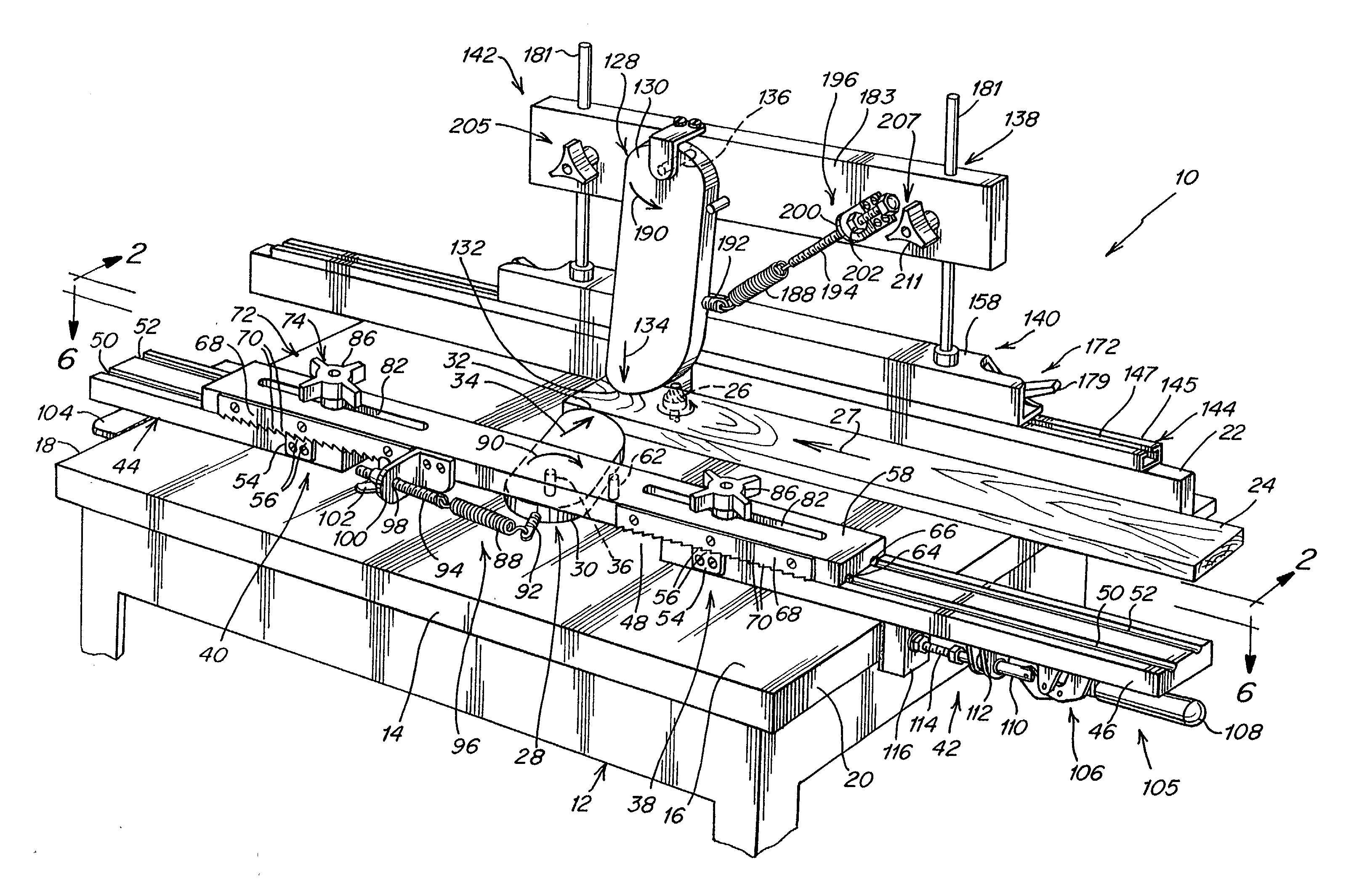
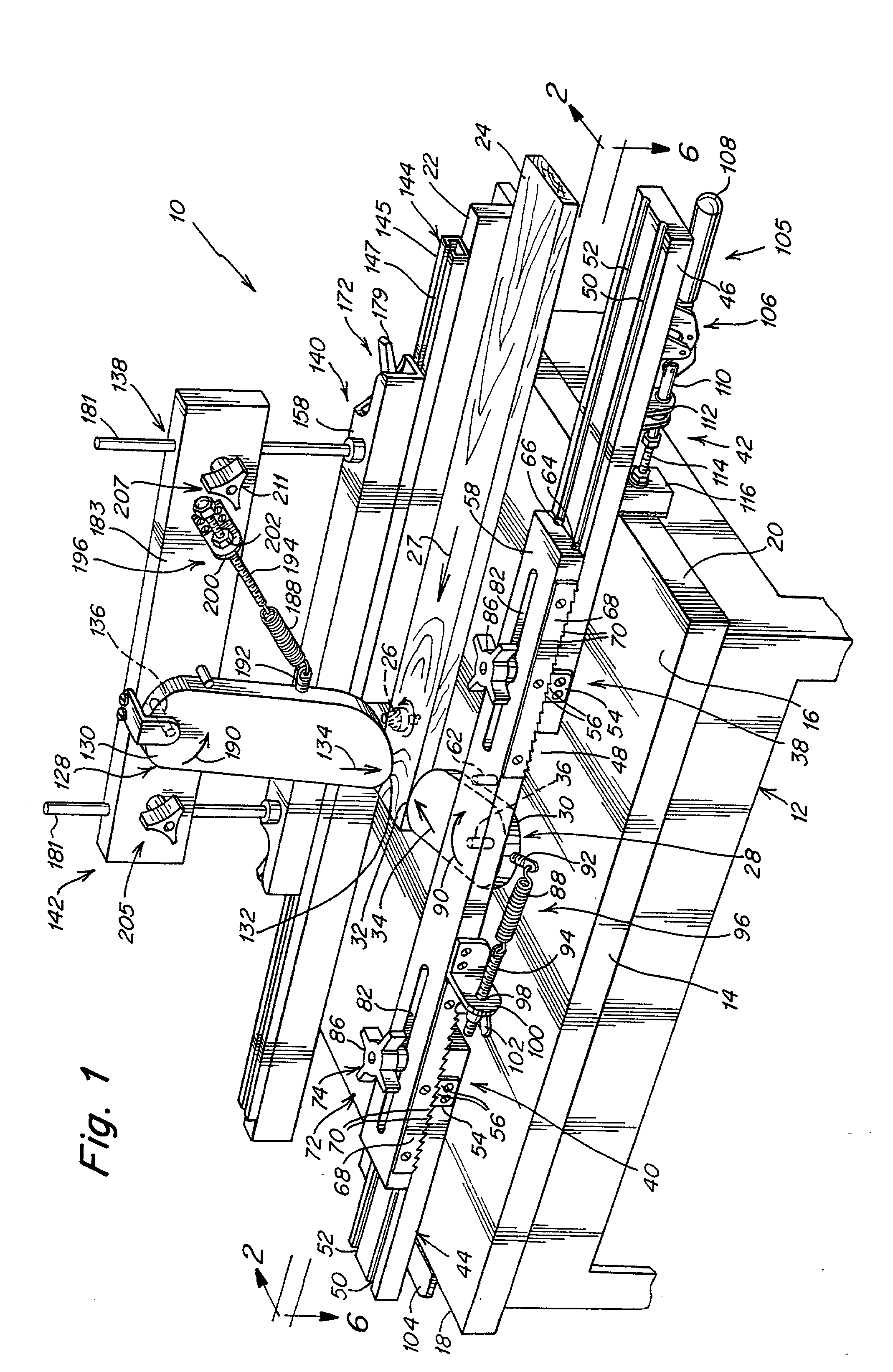
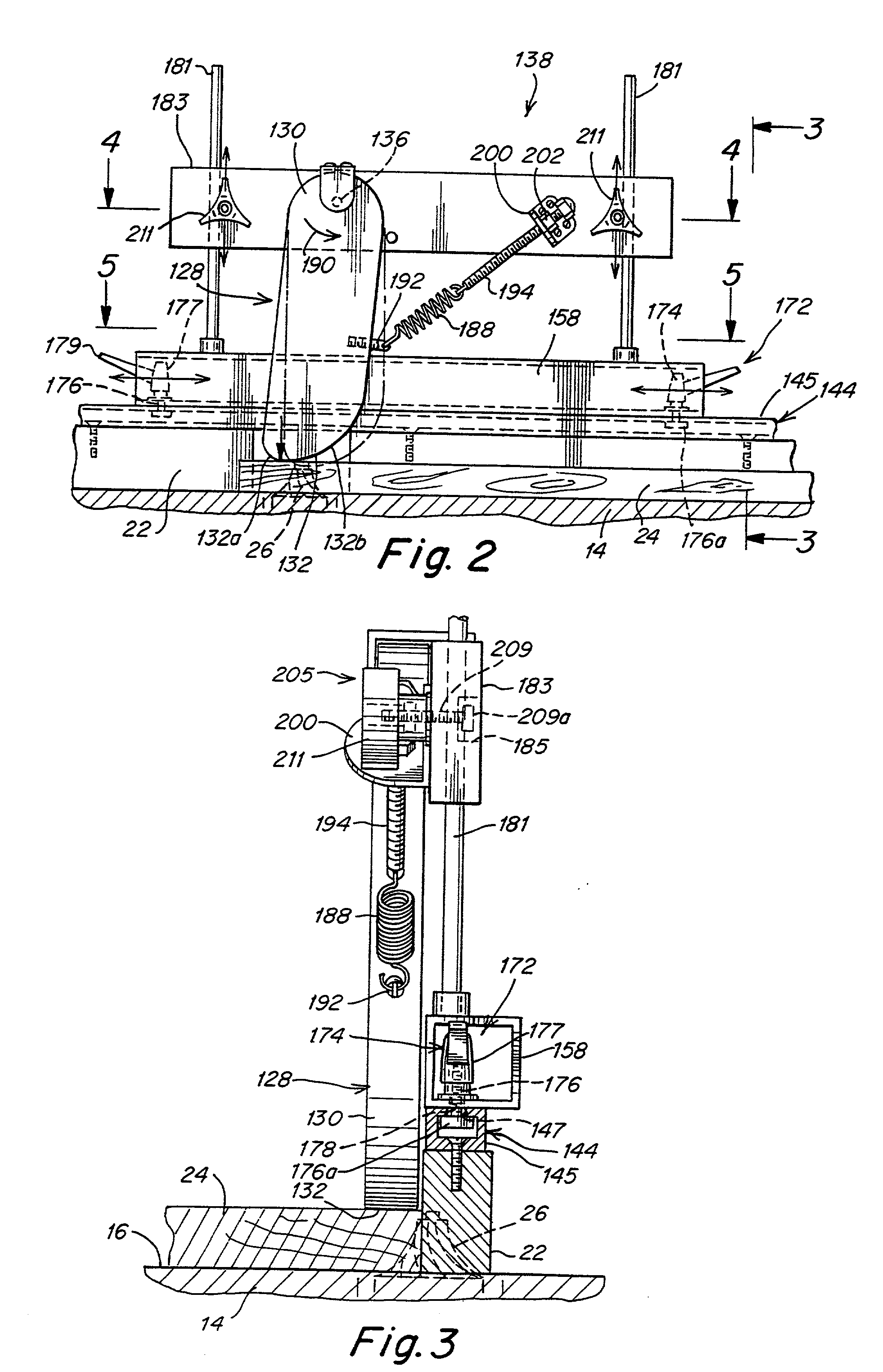
[0040] Referring to the drawings in detail, a combination workpiece positioning / hold-down and anti-kickback device 10 according to the present invention is designed for a use with a work table 12 having a tabletop 14 with an upper surface 16 and opposite transverse sides 18 and 20. As is conventional, a fence 22 is secured at one edge of work table 12. During operation, a workpiece 24, such as a piece of wood, is positioned on upper surface 16 and against fence 22. Then, a woodworking operation is performed by a woodworking tool such as a saw, router 26 and the like, while workpiece 24 is moved in the lengthwise direction 27 of work table 12, against fence 22.

[0041] In order to press workpiece 24 against fence 22, combination workpiece positioning / hold-down and anti-kickback device 10 includes a positioning member 28 having a main body 30 with a generally oblong shape, and an arcuate cam surface 32 at one shorter edge of main body 30 for engaging a side surface of workpiece 24 on wo...


PUM

PropertyMeasurementUnit
biasing forceaaaaaaaaaa
distanceaaaaaaaaaa
radiusaaaaaaaaaa

Abstract

A combination workpiece positioning, hold-down and anti-kickback device for a work table having a fence against which a workpiece is guided, includes a non-rotatable positioning member having an arcuate cam surface at one edge for engaging a side surface of a workpiece on the work table; an adjustment device for moving the positioning member in lengthwise and transverse directions relative to the workpiece and for locking the same thereat; a pivot pivotally mounting the positioning member to the adjustment device; a spring connected between the positioning member and the adjustment device for biasing the positioning member in a pivot direction into engagement with the side surface of the workpiece; a variable tensioning device for variably adjusting the biasing force of the spring; a non-rotatable hold-down member having a second arcuate cam surface at one edge for engaging an upper surface of the workpiece; an adjustment device for moving the hold-down member in lengthwise and vertical directions relative to the workpiece, and for locking the same thereat; a pivot pivotally mounting the hold-down member to the second adjustment device; a second spring connected between the hold-down member and the adjustment device for biasing the hold-down member in a second pivot direction into engagement with the upper surface of the workpiece; and a second variable tensioning device for variably adjusting the biasing force of the second spring.

Description

CROSS-REFERENCE TO RELATED APPLICATIONS[0001] This application claims the benefit under 35 USC 120 of application Ser. No. 09 / 482,772, filed Jan. 13, 2000, which claims the benefit of Provisional Application Serial No. 60 / 115,932 filed Jan. 14, 1999, the entire contents of which are incorporated herein by reference.BACKGROUND INFORMATION[0002] The present invention relates generally to work tables for power tools and the like, and is more particularly directed to a combination workpiece positioning / hold-down and anti-kickback device for a work table.[0003] A work table for a woodworking device, such as a power saw, router and the like, generally includes a horizontal tabletop on which the workpiece is supported and a fence secured to the tabletop and extending in the direction of movement of the workpiece. The workpiece is moved on the upper surface of the tabletop and is guided along the fence, during a cutting or other woodworking action.[0004] Featherboard and other devices are k...

Claims


Application Information

Patent Timeline
Patent Type & Authority Applications(United States)
IPC IPC(8): B23D47/04B23Q3/00B27B29/00B27C5/06B27G19/02B27G21/00
CPCB23D47/04B23Q3/002B27B29/00B27C5/06B27G19/02B27G21/00
Inventor JUKOFF, PETER
Owner JUKOFF PETER
Learn More