
4-port wavelength selective router

a wavelength selective router and router technology, applied in multiplex communication, instruments, optical elements, etc., can solve the problems of relative intensity noise, optical back reflection in bidirectional transmission systems, and inability to remove multiple reflected lights

Inactive Publication Date: 2002-03-07
KOREA ADVANCED INST OF SCI & TECH
View PDF4 Cites 17 Cited by
  • Summary
  • Abstract
  • Description
  • Claims
  • Application Information

AI Technical Summary

Problems solved by technology

However, the bidirectional transmission systems suffer from the optical back reflections.
However, we cannot remove the multiple reflected lights in such a way and the multiple reflected lights causes a relative intensity noise.
Thus the relative intensity noise limits the maximum available amplifier gains of the bidirectional transmission systems and networks.
However, the optical filter installed at the receiver (RX) cannot remove the multiple reflected noisy lights because their wavelengths are same as those of the signal lights.

Method used


Image

  • 4-port wavelength selective router
  • 4-port wavelength selective router
  • 4-port wavelength selective router

Examples


Embodiment Construction

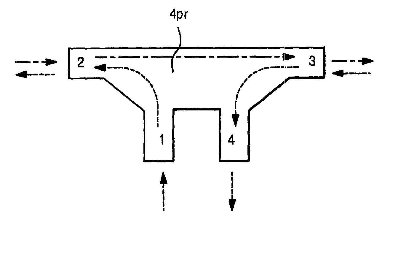
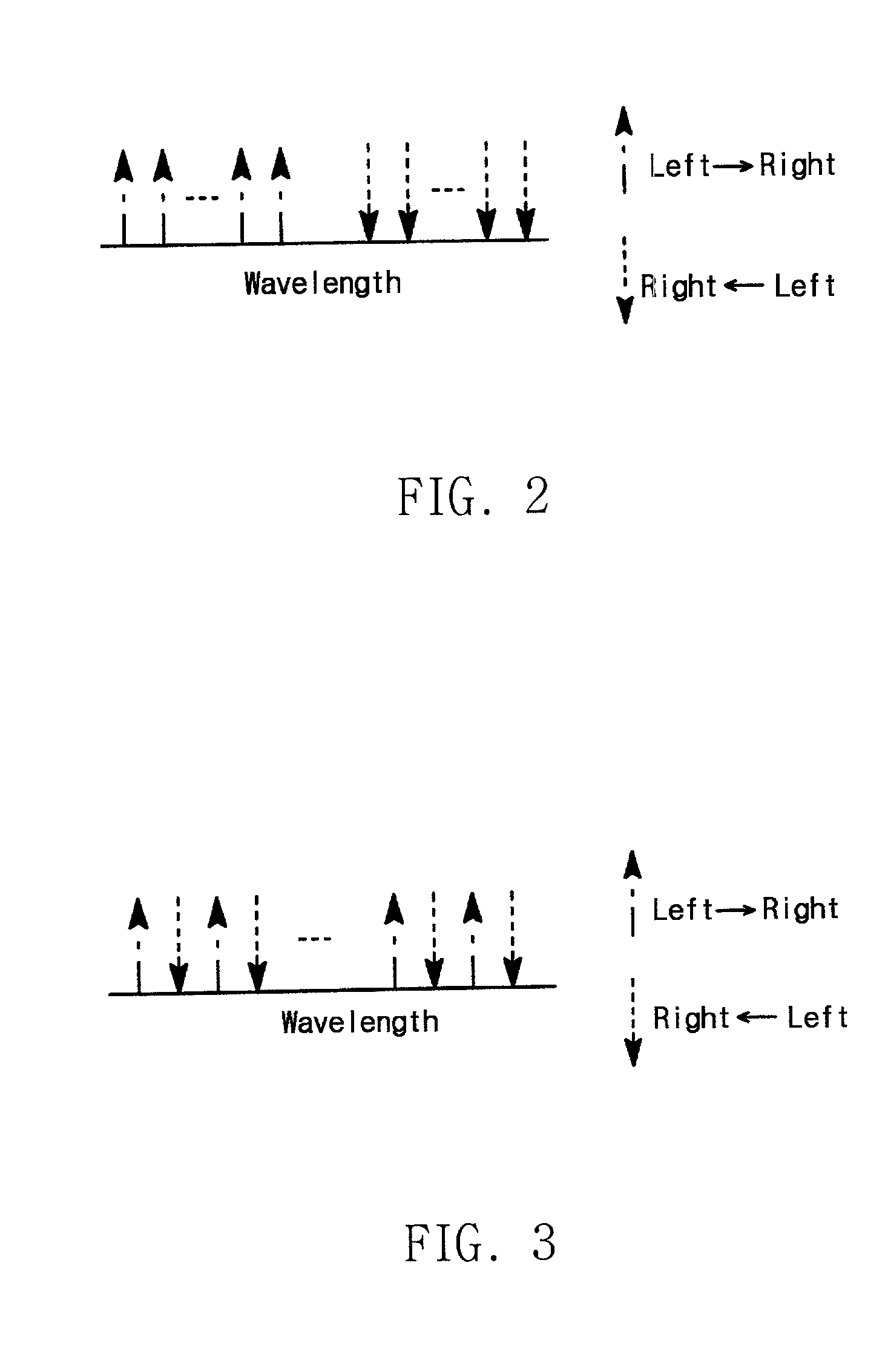
[0035] The 4-port wavelength selective router (4pr) in accordance with the present invention is used in order to effectively route two groups of counter-propagating signals over a single optical fiber and also to suppress the relative intensity noise induced by multiple back reflections. The above two groups are defined as follows: the first group (Group A) consists of one or more optical signals of different wavelengths. The second group (Group B) consists of one or more optical signals of different wavelengths excluding the signals included in Group A. Here the methods for dividing the optical signals (Group A, Group B) are above mentioned band split scheme or wavelength-interleaved scheme.

[0036] As shown in FIG. 5, the 4-port wavelength selective router (4pr) has 4 ports (1, 2, 3, 4). Thus the possible combinations of port pairs are 6 in total ((1,2), (2,3), (3,4), (1,3), (2,4), (1,4)). The internal signals transmission paths exist between port pairs (1) and (2), ports (2) and (3...


PUM


Abstract

The present invention relates to a 4-port wavelength selective router and the add / drop multiplexer using the above router. More particularly, it relates to a 4-port wavelength selective router that can effectively routes counter-propagating signals while suppressing multiple reflections generated in the bidirectional transmission systems and networks.

Description

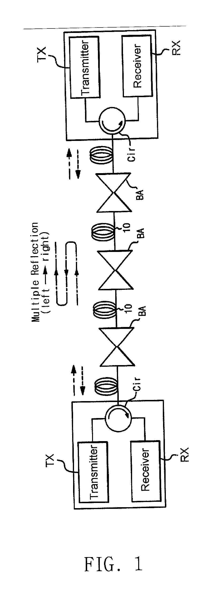
[0001] 1. Field of the Invention[0002] The present invention relates to a 4-port wavelength selective router that routes the counter-propagating signals while suppressing relative intensity noise induced by the multiple back reflections in the bidirectional transmission systems and networks.[0003] 2. Description of the Related Art[0004] The bidirectional signal transmission over a single fiber is advantageous compared with the unidirectional signal transmission. It enables full-duplex communications between two nodes with a single strand of optical fiber. It also alleviates the nonlinear effects of optical fiber and thereby enables to achieve higher spectral efficiency.[0005] However, the bidirectional transmission systems suffer from the optical back reflections. In bidirectional transmission systems, the counter-propagating signals are usually allocated at different wavelengths. Thus, we can suppress the reflected light by using optical filters at the receiver. However, we cannot ...

Claims


Application Information

Patent Timeline
Patent Type & Authority Applications(United States)
IPC IPC(8): G02B6/28G02B6/26G02B6/34H04B10/25H04J14/02H04Q11/00
CPCG02B6/2746G02B6/29361G02B6/29383G02B6/29386G02B6/34H04B10/2504H04J14/0206H04J14/0208H04J14/0212H04J14/0213H04Q11/0005H04Q2011/0024H04Q2011/0032H04Q2011/0035H04B10/25891G02B6/28
Inventor LEE, CHANG HEEKIM, HYUN DEOKOH, TAE WONHUN, SHIN JEONGHEE, CHO YUN
Owner KOREA ADVANCED INST OF SCI & TECH
Learn More