
Low speed steering system

Inactive Publication Date: 2002-02-07
BRP US
View PDF0 Cites 1 Cited by
  • Summary
  • Abstract
  • Description
  • Claims
  • Application Information

AI Technical Summary

Benefits of technology

[0013] It is an even further object of the invention to provide an electronic control means within the steering system for applying a minimal thrust to the jet propulsion unit. At such time as the throttle is set to an off position, the electronic control means may provide a minimal thrust to the jet propulsion unit for enhancing docking and other directional movements of the watercraft vehicle.
[0017] In accordance with the invention, these and other objectives are achieved by providing a low speed steering system comprising a novel means for controlling the thrust of the water exiting the jet propulsion unit for enhancing docking and other directional control movements of a watercraft vehicle. Accordingly, the novel low speed steering system configuration enables an operator of the vehicle to directionally control steering of the watercraft vehicle by means of the steering helm assembly when the throttle is set in an off position.

Problems solved by technology

However, none of the patents disclose a means for controlling movement of the watercraft vehicle at low speeds by means of activating and controlling the carburetor and the air-fuel mixture being supplied to the carburetor.
Furthermore, the Prior Art fails to disclose means for controlling the thrust and directional control of the vehicle at low speeds through the exclusive use of the steering helm assembly.

Method used


Image

  • Low speed steering system
  • Low speed steering system
  • Low speed steering system

Examples


Embodiment Construction

[0026] Although the disclosed invention may have broad applicability, it relates primarily to an apparatus for controlling steering of a watercraft vehicle at low speeds and more specifically to a personal watercraft vehicle or similarly powered watercraft vehicle. This invention is applicable to all watercraft vehicles propelled by means of a jet propulsion unit, including those configured with an impeller as well as those configured with an outboard motor. The following description will indicate certain items as occurring in pairs when either one or both items are shown in the accompanying drawings. It is to be understood that the portion of each pair which is not shown is identical to the illustrated part and performs the same function as the illustrated item. Accordingly, it should be noted that like reference numerals are used throughout the attached drawings to designate the same or similar elements or components.

[0027] In a conventional watercraft vehicle, it is difficult to ...


PUM


Abstract

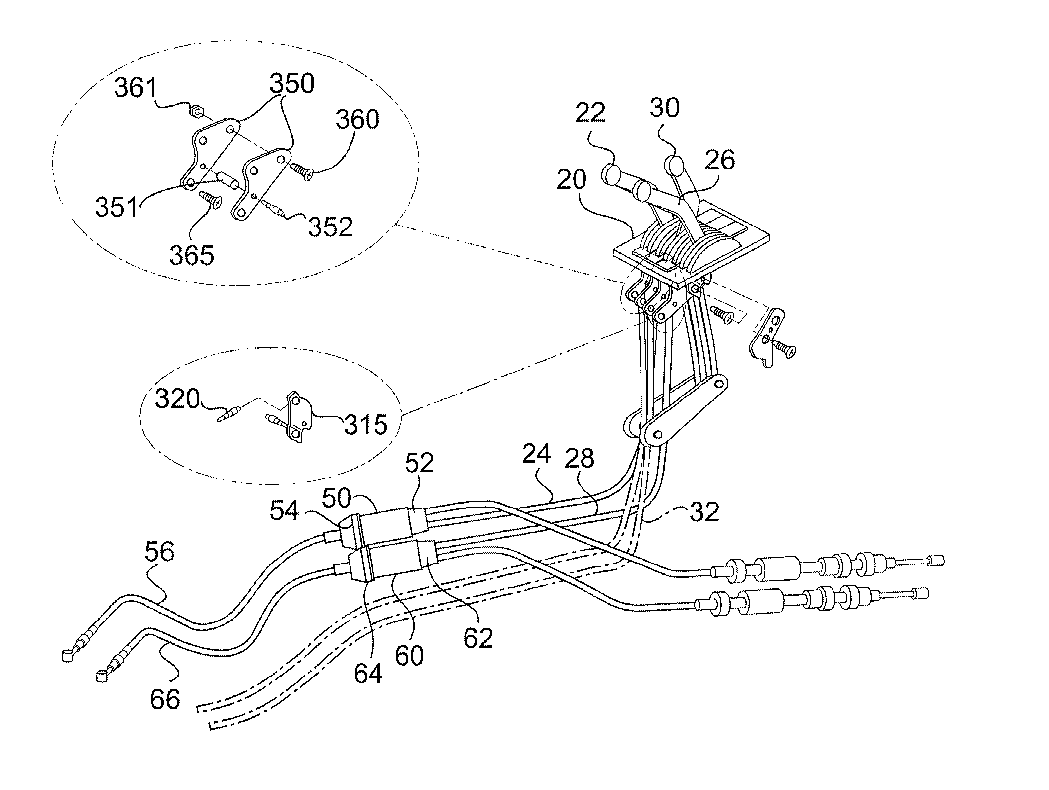
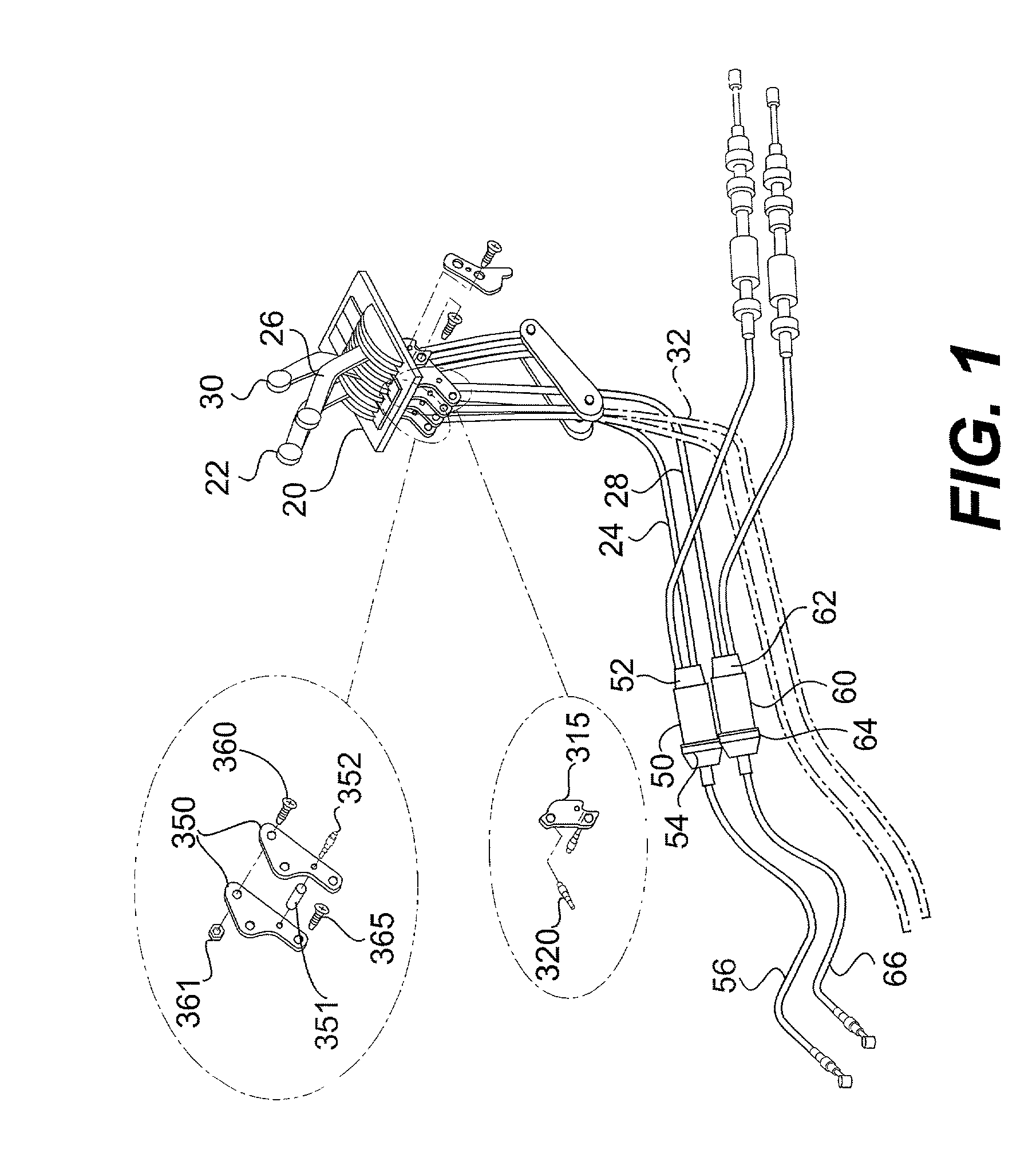
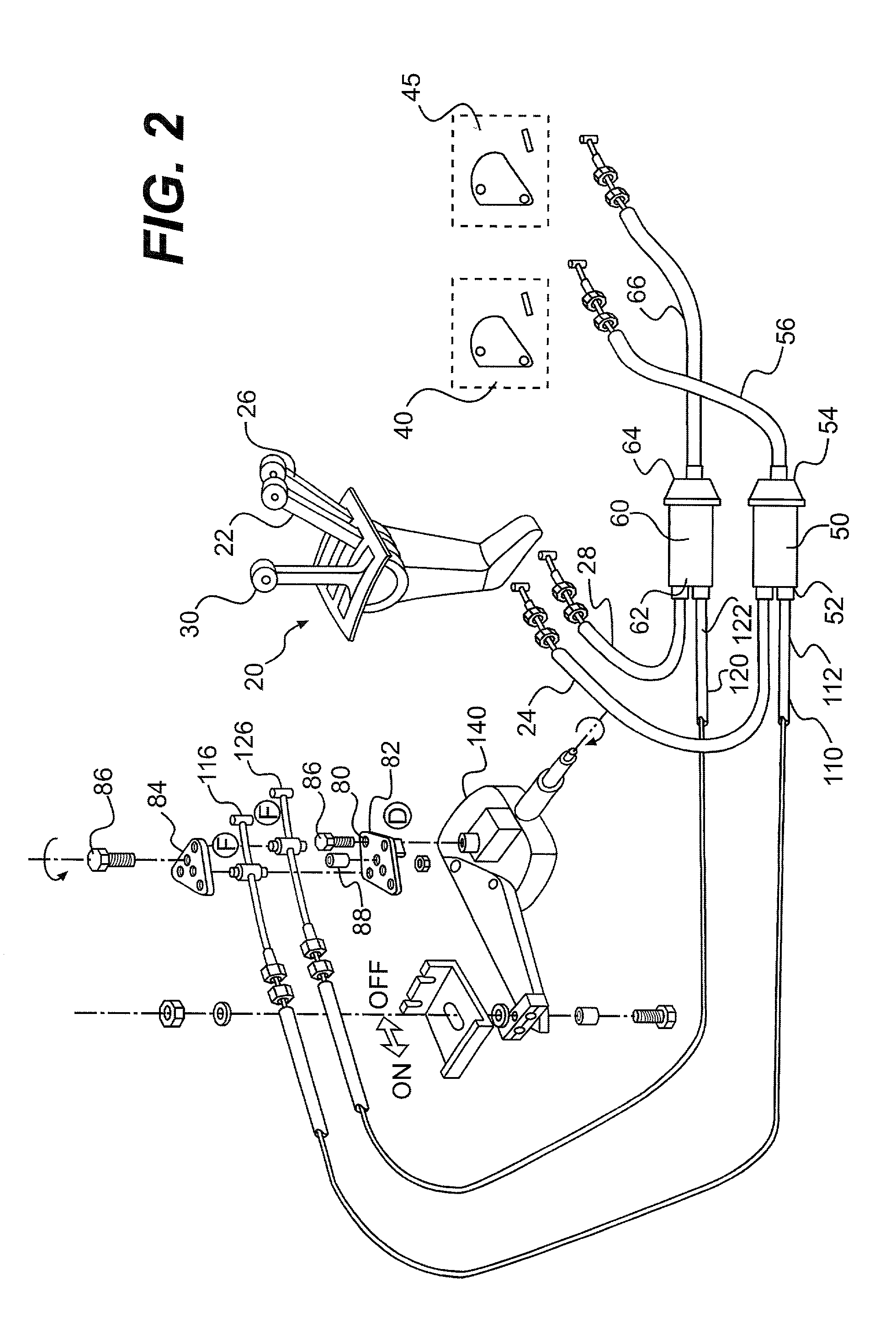
The invention relates to a low speed steering system for a watercraft vehicle having a jet propulsion unit, or a similarly powered vehicle, which allows the operator of the vehicle to control maneuvering of the vehicle at low speeds. The low speed steering system is comprised of a plurality of cables, slide couplers, and a cable support. At such time as the vehicle throttle lever is set to an off position, the engine is calibrated so that it idles, and the engine speed and the thrust of the water exiting the venturi and exit nozzle may be controlled by the vehicle steering helm assembly. As the steering helm assembly is rotated, a set of cables extending from the cable support adjacent to the steering helm assembly activates the vehicle engine. Upon rotation of the steering wheel a given degree in a clockwise or counter-clockwise direction from a straight alignment of the vehicle, a set of cables extending from the cable support to the slide couplers activates the vehicle engine. Rotation of the steering wheel a given degree in a clockwise or counter-clockwise direction increases engine speed from about 0 to about 3,000 revolutions per minute, and produces a thrust exiting the jet propulsion unit from about 0 to about 50 pounds. The rotation of the steering helm assembly a given degree in a clockwise direction produces a sufficient amount of power to enable the operator of the vehicle to manage docking and careful maneuvering of the watercraft vehicle in a rightward direction. In an alternative embodiment, the steering system may comprise a plurality of sensors, switches, and electrical wiring for detecting the engine speed and position of the steering helm assembly. The electronic apparatus function to activate the carburetor biasing means and provide low speed directional control of the watercraft vehicle.

Description

[0001] 1. Field of the Invention[0002] This invention relates to a low speed steering system for a watercraft vehicle powered by a jet propulsion unit. More particularly, this invention relates to a novel apparatus for controlling steering and movement of a watercraft vehicle at low speeds and a means for controlling the thrust of the water exiting the jet propulsion unit at corresponding low engine speeds.[0003] 2. Discussion of Related Art[0004] Directional control of watercraft vehicles depend upon the thrust of the water exiting a jet propulsion unit. As the thrust of the water exiting the venturi and the exit nozzle of the jet propulsion unit decreases so does the engine speed of the watercraft vehicle. A conventional jet propulsion unit 210 for a watercraft is shown in FIG. 7 and is comprised of an inner housing and an outer housing. The outer housing comprises a water inlet portion 215 for allowing water into the propulsion unit. At low speed, the jet propulsion unit 210 crea...

Claims


Application Information

Patent Timeline
IPC IPC(8): B63H21/22F02B61/04F02D11/02G05G11/00
CPCB63H21/21B63H21/22F02B61/045F02D11/02G05G11/00
Inventor RHEAULT, ALAINMICHEL, CAMILLE
Owner BRP US
Learn More