Connecting structure for battery terminals

a technology of connecting structure and battery terminal, which is applied in the direction of connection contact material, cell component, coupling device connection, etc., can solve the problems of high-voltage battery, increase the seriousness of problems, and electrical backflow

Inactive Publication Date: 2001-12-06
YAZAKI CORP
View PDF0 Cites 13 Cited by
  • Summary
  • Abstract
  • Description
  • Claims
  • Application Information

AI Technical Summary

Benefits of technology

[0023] This prevents one hand of a worker from being used for supporting the battery terminal during an operation of fastening the battery terminal by the screw members, one hand of a worker is used for supporting the battery terminal. Consequently, the worker can easily perform the screwing operation by freely using both hands.
[0025] This prevents the circumferential portion, which is rubbed when the battery terminal is inserted into or detached from the accommodation space, of each of the terminal insertion openings from wearing down and eroding during the attachment / detachment of the battery terminal. Additionally, this prevents the terminal insertion openings from being deformed.

Problems solved by technology

Thus, there is a fear that electric backflow caused by the miscontact may break the equipment.
However, the implementation of a high-voltage battery increases the degree of seriousness of the problems of accidents due to the miscontact and sparks due to an arc.
Furthermore, recent increase in the power consumption of per vehicle results in increase in the number of batteries mounted on a vehicle.
Consequently, this battery terminal cannot be fitted into this terminal insertion opening.
Moreover, even the contact between this battery terminal and the battery electrode provided in the accommodation space, which is surrounded by the insulating wall portion, cannot be achieved.

Method used


Image

  • Connecting structure for battery terminals
  • Connecting structure for battery terminals
  • Connecting structure for battery terminals

Examples


first embodiment

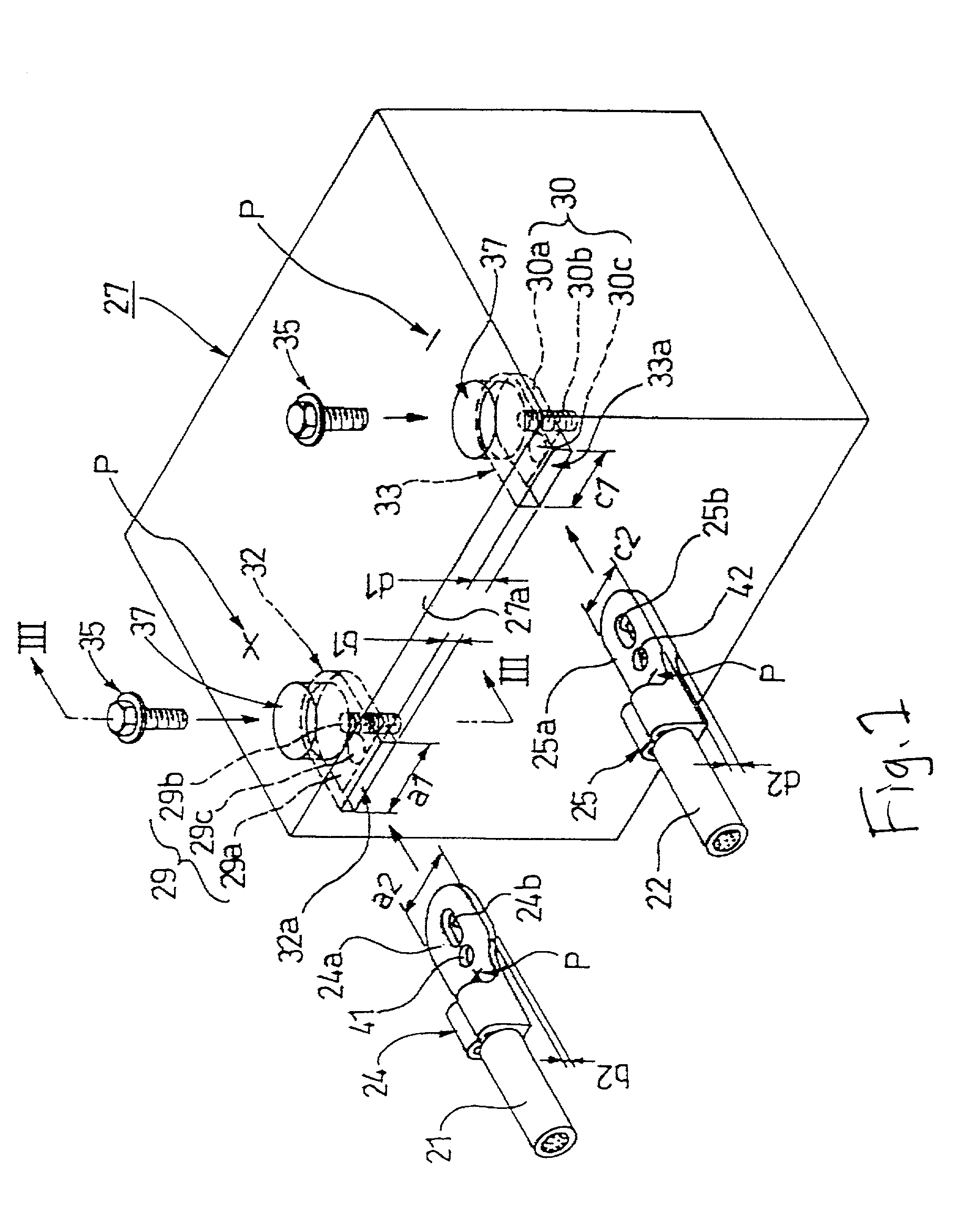
[0033] FIG. 1 is a perspective view illustrating the entire battery body having a connecting structure for battery terminals according to the invention. FIG. 2 is a perspective view illustrating a primary part of the battery body shown in FIG. 1. FIG. 3 is a sectional view taken along line III-III of FIG. 1.

[0034] As shown in FIG. 1, the connecting structure for battery terminals is adapted to establish the electrical connection between the battery terminals and the battery electrodes by fastening and fixing each of battery terminals 24 and 25 to one of battery electrodes 29, 30 by using a bolt 35 serving as a screw member. The battery electrodes 24 and 25 respectively correspond to the positive polarity and the negative polarity and are connected to the end portions of the wires 21 and 22. Each of the battery electrodes 29, 30 is of corresponding polarity.

[0035] The battery 27 has two accommodation spaces 32, 33 surrounded by an insulating wall portion 27a of the outer wall thereof...

second embodiment

[0057] FIG. 4 shows a connecting structure for battery terminals, which is the invention, is constructed so that the battery electrode 46 provided in the accommodation space 45 of the battery body 50 comprises an electrode post 47 serving as a male screw member, which is provided in such a manner as to extend in a direction perpendicular to a pedestal made of an electrically conductive material.

[0058] Moreover, a notch 48a, through which the electrode post 47 penetrates, is formed in the connecting flat plate portion 48a of the battery terminal 48 connected to the end portion of the wire 21.

[0059] Thus, the battery terminal 48 is electrically connected to the battery electrode 46 of the corresponding polarity by fastening and fixing the connecting flat plate portion 48a, which is fitted into the accommodation space 45 from the corresponding terminal insertion opening 45a of the battery body 5, to the electrode 46 with a nut 49 serving as a screw member.


PUM


Abstract

A battery body (27) has positive and negative battery electrodes (29, 30), which are provided in two accommodation spaces (32, 33) surrounded by an insulating wall portion (27a) that is an outer wall thereof, and also has terminal insertion openings (32a, 33a) adapted to permit only battery terminals, which correspond to the battery electrodes (29, 30) accommodated in the accommodation spaces (32, 33), respectively, to be fitted thereto. Each of the battery terminals (24, 25) has a connecting flat plate portion (24a, 25a) that has a transversal section of a predetermined shape and can be fitted into a corresponding one of the terminal insertion opening (32a, 33a). One of the terminal insertion openings (32a) has a nearly rectangular opening having an opening width (a1), which is wider than an opening width (c1) of the other terminal insertion opening (33a), and also having an opening height (b1), which is lower than an opening height (d1) of the latter terminal insertion opening (33a).

Description

[0001] 1. Technical Field of the Invention[0002] The present invention generally relates to a connecting structure for battery terminals and, more particularly, to a connecting structure for surely connecting battery terminals to battery electrodes of corresponding polarity of a battery body mounted on a vehicle without miscontact of the battery terminals with the battery electrode.[0003] 2. Related Art[0004] FIGS. 5 and 6 illustrate a related connecting structure for fastening and fixing battery terminals, provided at an end of an electric wire connected to various kinds of electrical equipment, to battery electrodes of a battery body, mounted on a vehicle, by screw members.[0005] This connecting structure for a battery terminal is disclosed in JP-A-4-220947, and configured so that a positive battery electrode 3 and a negative battery electrode 4 of the vehicle-mounted battery body 1 are quadrangular-prism-like posts 3b and 4b respectively erected on base potions 3a and 4a on the t...

Claims


Application Information

Patent Timeline
IPC IPC(8): H01R4/34H01M2/02H01M2/30H01M2/34H01R4/28H01R4/58
CPCH01M2/307H01M50/561Y02E60/10
Inventor HASEGAWA, TETSUYATAMAI, YASUHIRO
Owner YAZAKI CORP
Why Eureka
Try Eureka