
Device for raising at least one binding element used on a board for gliding

a technology of binding elements and devices, applied in the field of boards for gliding, can solve the problems of generating clamping of boards, not being able to transmit sufficiently effective bearing forces,

Inactive Publication Date: 2001-11-22
LOOK FIXATIONS
View PDF0 Cites 6 Cited by
  • Summary
  • Abstract
  • Description
  • Claims
  • Application Information

AI Technical Summary

Benefits of technology

[0017] Under these conditions, the bearing forces are exerted in a longer zone of the underboot section, which allows an efficient turn initiation and better control through the turn.
[0020] In other words, the presence of an elastic material makes the raising device and thus the entire board more dynamic by opposing flexing in the bearing zone.
[0026] In other words, when the board is significantly bent, the end of the bearing zone may slide slightly relative to the upper face of the board in order to prevent longitudinal forces being exerted on the board.
[0029] In this case, this layer of viscoelastic material efficiently transmits forces which are exerted vertically, and works in shear when the bearing zone tends to be displaced longitudinally.

Problems solved by technology

On account of the flexibility of the longitudinal tongues, such a device does not make it possible to transmit sufficiently effective bearing forces, in particular when the skier exerts forces at the location of one of the elements of the binding.
Moreover, the presence of elastomeric blocks tends to damp the behavior of the board overall, so such devices are intended more for relatively soft skis and, conversely, very dynamic skis, in particular those used in competition.
Indeed, the attaching means have the essential function of transferring a portion of the vertical forces exerted by the skier and must not secure the raising device via two ends, at the risk of generating clamping of the board.

Method used


Image

  • Device for raising at least one binding element used on a board for gliding
  • Device for raising at least one binding element used on a board for gliding

Examples


Embodiment Construction

[0039] As already stated, the invention relates to a raising device designed to be placed on a board for gliding such as, in particular, a downhill ski.

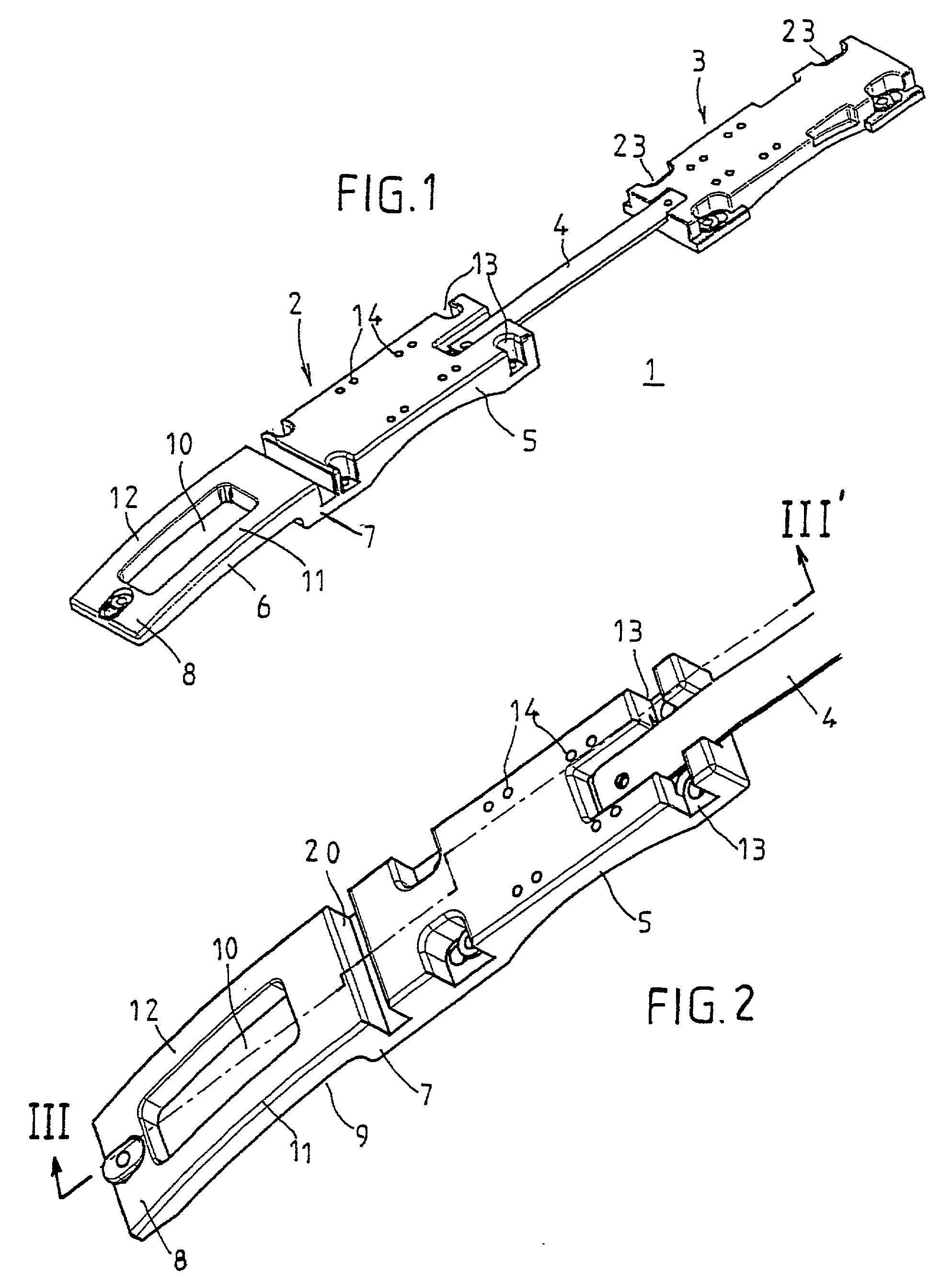
[0040] Several different architectures may be employed while remaining within the spirit of the invention, and the latter is not limited to the single embodiment illustrated in FIG. 1.

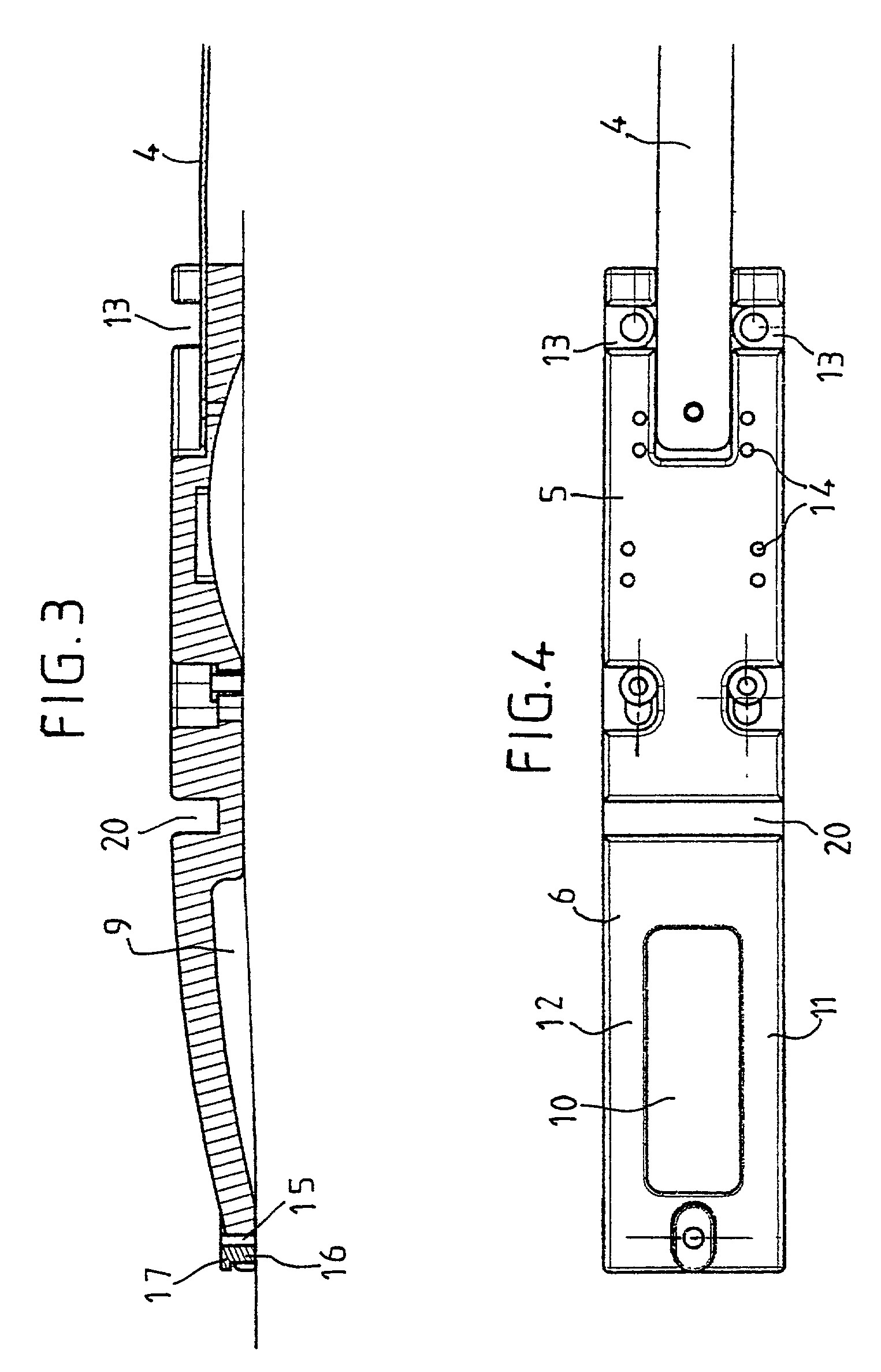
[0041] Thus, as illustrated in FIG. 1, the raising device (1) comprises a front part (2) and a rear part (3) which are connected by a rigid tongue (4). The front part (2) includes a zone (5) for mounting the binding and a bearing zone (6).

[0042] Naturally, the invention is not limited to this particular geometry, but also covers variants in which the characteristic zone (2) receives the heelpiece of the binding instead of the stop.

[0043] Moreover, the invention also covers variants in which the raising device includes two characteristic zones, each including a bearing zone, associated with the stop and the heelpiece of the binding.

[0044] Returning to th...


PUM


Abstract

A device (1) for raising at least one element of a binding used on a board for gliding, including: a zone (5) for mounting the binding, integral with the board for gliding; a bearing zone (6), extending the mounting zone (5) in the direction of the end of the board, wherein the end (8) of the bearing zone facing toward the end of the board is secured to the upper face of the board by attaching means (16) in such a manner that the forces exerted at the location of the element of the binding are partially transmitted to the board at the location of said end (8) of the bearing zone (6), and which includes a transverse groove (20) located between the mounting zone (5) and the bearing zone (6) so as to allow the deformation of the bearing zone (6) when the board is bent.

Description

[0001] The invention relates to the field of sports involving gliding over snow.[0002] It relates more particularly to the devices used on skis and, in particular, downhill skis.[0003] It refers more specifically to devices for raising bindings, making it possible to optimize the transmission of the bearing forces exerted by the skier toward the board.PRIOR ART[0004] In a known manner, boards for gliding and, in particular, downhill skis include safety bindings consisting of a stop which interacts with the toe of the boot and a heelpiece holding the rear of the boot.[0005] It is already known to mount the binding elements on raising platforms, the aim of which is to elevate the boot above the board for gliding. This is particularly advantageous when the board for gliding has a relatively pronounced sidecut, and it is thus necessary to prevent the boot coming into contact with the snow when the board is inclined laterally.[0006] Other raising platforms have already been proposed to p...

Claims


Application Information

Patent Timeline
Patent Type & Authority Applications(United States)
IPC IPC(8): A63C9/00
CPCA63C9/003
Inventor KRAUAJITCH, ANDRE-JEAN
Owner LOOK FIXATIONS
Learn More