Body part for a motor vehicle with positioning structure

Active Publication Date: 2022-11-08
CO PLASTIC OMNIUM +1
View PDF20 Cites 0 Cited by
  • Summary
  • Abstract
  • Description
  • Claims
  • Application Information

AI Technical Summary

Benefits of technology

[0004]To address such problems in the prior art as easy deformation of the positioning holes and as imprecise positioning by the positioning ribs, the present invention is to provide a body part for a motor vehicle with one combined positioning structure integrating the functions of both the positioning holes and the positioning ribs.
[0020]The positioning structure of the present invention combines the arrangements of both the positioning holes and the positioning ribs in the prior art. The positioning structure acts on the one hand a clamping seat for its positioning on the painting rack and on the other hand a positioning rib used for the pre-positioning of the inner panel relative to the outer panel before their welding assembly. Moreover, the structural configuration of the positioning structure provide an easier and more stable positioning effect for both operations of placing the outer panel on the rack and pre-assembling the inner panel with the outer panel, thereby greatly enhancing the eligibility rate of spray painting and welding stability. In addition, the positioning structure of the present body part may support the body part by four legs, which is structurally strength and has a good positioning effect.

Problems solved by technology

Apparently, the positioning hole 11 used for positioning tends to be deformed easily, which may lead to a low eligibility rate of spray painting.
Further, the positioning hole 11 is usually in small size, so that it is really hard to align the positioning hole 11 with the rack while hanging the outer panel 1 on the rack, which leads to difficulty in operation.

Method used


Image

  • Body part for a motor vehicle with positioning structure
  • Body part for a motor vehicle with positioning structure
  • Body part for a motor vehicle with positioning structure

Examples


Embodiment Construction

[0034]The preferred embodiment of the present invention will be described in detail for a rear spoiler of a motor vehicle with reference to the drawings. It can be understood that other examples for a vehicle body part consisting of an outer panel and an inner panel which are assembled together, such as a front / rear bumper, a tailgate, or a door, etc., fall within the protection scope of the present invention.

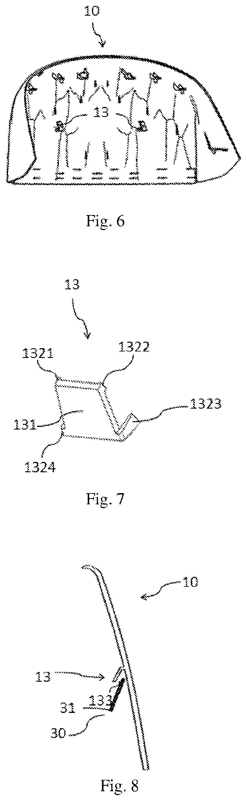
[0035]FIG. 6 is a schematic view of the backside of the outer panel of the spoiler according to the present invention. The backside of the outer panel 10 is provided with two symmetric clamping seats 13.

[0036]FIG. 7 is an enlarged view of the clamping seat. The clamping seat 13 comprises a quadrangular plate 131 spaced from the backside of the outer panel 10, and the quadrangular plate 131 is connected to the backside of the outer panel 10 by four legs 1321, 1322, 1323, 1324, wherein the first leg 1321 and the second leg 1322 have a substantially equal first length, the third l...


PUM


Abstract

A body part for a motor vehicle with a positioning structure is provided. The body part includes an outer panel and an inner panel, and a backside of the outer panel is provided with a positioning structure to position the outer panel relative to the inner panel for their assembly, the positioning structure including a clamping seat configured to receive a shaft of a rack for positioning the outer panel thereon during manufacturing of the outer panel, and to be engaged in an opening of the inner panel to position the outer panel relative to the inner panel. The positioning structure combines the arrangements of both positioning holes and positioning ribs, thereby greatly enhancing the eligibility rate of spray painting and welding stability.

Description

FIELD OF THE INVENTION[0001]The present invention relates to a body part for a motor vehicle, and more particularly to a vehicle body part with a positioning structure.BACKGROUND OF THE INVENTION[0002]A body part for a motor vehicle is generally in assembled structure, comprising an outer panel 1 and an inner panel 2, for instance a spoiler installed in the rear of a vehicle as shown in FIG. 1. To ensure that the outer panel 1 has a colour identical with or matching that of the car body, the outer panel 1 must be hanged on a rack for spray painting during the production. In the prior art, a positioning hole 11 is arranged in the backside of the outer panel 1 and in an area adjacent to the edge, as shown in FIG. 2, thereby positioning the outer panel 1 on the rack through the positioning hole 11 for spray painting. Apparently, the positioning hole 11 used for positioning tends to be deformed easily, which may lead to a low eligibility rate of spray painting. Further, the positioning ...

Claims


Application Information

Patent Timeline
Patent Type & Authority Patents(United States)
IPC IPC(8): B62D35/00B62D65/02B62D37/02B62D65/16
CPCB62D35/007B62D37/02B62D65/024B62D65/16Y02T10/82
Inventor LUO, XIAOHUI
Owner CO PLASTIC OMNIUM
Why Eureka
Try Eureka