
Vehicle-body structure of vehicle

Active Publication Date: 2022-11-08
MAZDA MOTOR CORP
View PDF3 Cites 0 Cited by
  • Summary
  • Abstract
  • Description
  • Claims
  • Application Information

AI Technical Summary

Benefits of technology

The present invention is aimed at improving the safety performance of vehicles in the event of a frontal collision and the comfort performance during normal driving. It provides a vehicle-body structure that can enhance both the pedestrian protection and the NVH performance. The invention includes a reinforcing member with an open section portion that increases rigidity to suppress vibration during normal traveling and breaks securely during a collision load input. Additionally, the lower end part of the side wall section is designed to prevent improper breaking during a collision, resulting in efficient energy absorption without hindering the proper deformation of the cowl panel. Overall, the invention ensures the safety and comfort of vehicles during collisions while maintaining their performance during normal driving.

Problems solved by technology

Meanwhile, the above-described easy deformation of the cowl panel may cause improper vibrations of the vehicle transmitted from a powertrain at a vehicle normal traveling.
Accordingly, when the cowl panel vibrates, the windshield vibrates as well, so that booming noise may occur in a cabin of the vehicle.
Consequently, there is a concern that the NVH (Noise, Vibration, Harshness) performance of the vehicle may be deteriorated.
On the other hand, there is a concern that this crushing deformation of the bending portion (200s) may cause the reinforcing member to vibrate improperly at the vehicle normal traveling.

Method used


Image

  • Vehicle-body structure of vehicle
  • Vehicle-body structure of vehicle
  • Vehicle-body structure of vehicle

Examples


Embodiment Construction

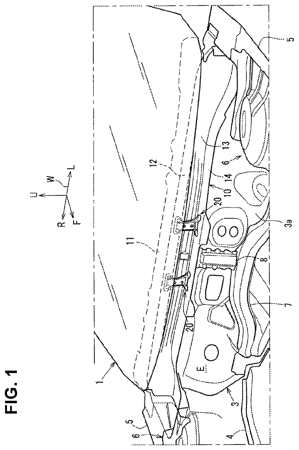
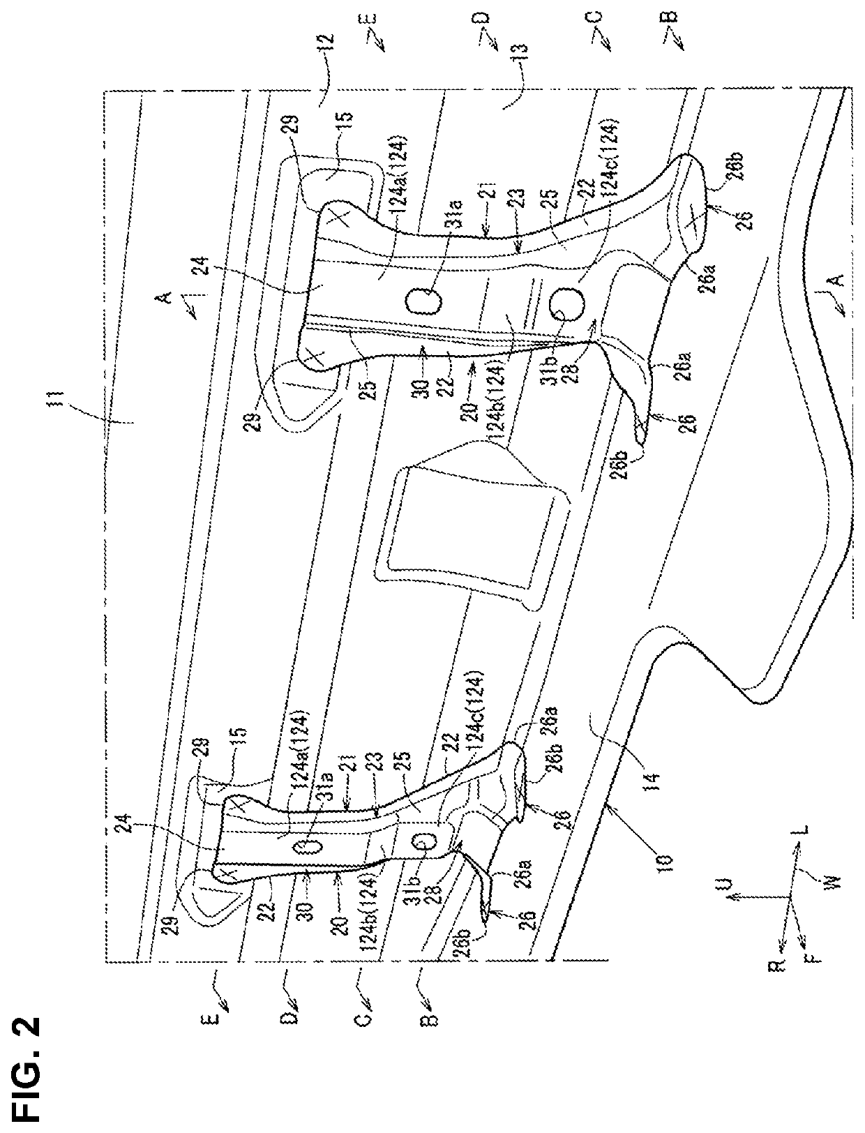
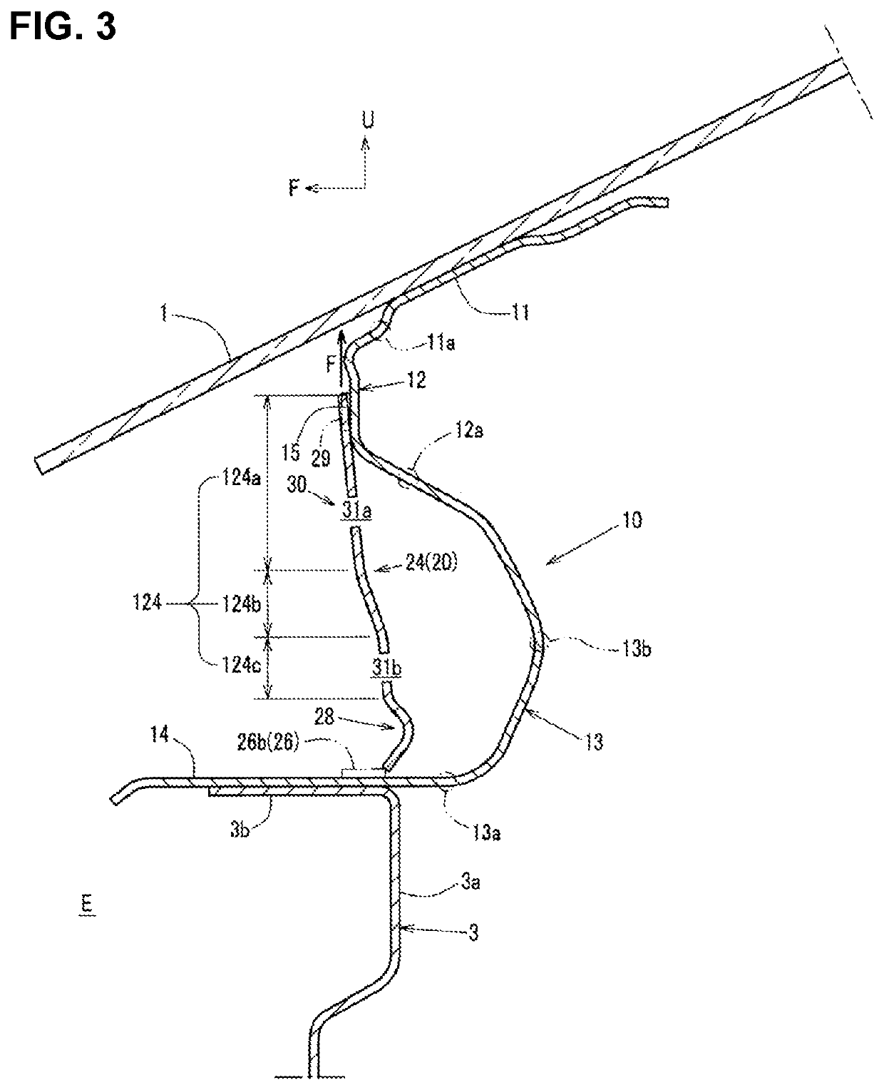
[0037]Hereafter, an embodiment of the present invention will be described specifically. FIG. 1 is a perspective view of a major part of a vehicle-body structure of the present embodiment, when viewed obliquely from a forward, leftward and upward side, FIG. 2 is an enlarged perspective view of a cowl panel and a reinforcing member of the present embodiment, when viewed obliquely from the forward, leftward and upward side, and FIG. 3 is a sectional view taken along line A-A of FIG. 2. FIG. 4 is an elevational view of the reinforcing member of the present embodiment, specifically, the elevational view of the reinforcing member, when viewed from a slightly leftward side. FIG. 5 is a left-side face view of the reinforcing member of the present embodiment, specifically, the left-side view of the reinforcing member, when viewed obliquely from a slightly rearward and upward side. FIG. 6A is a sectional view taken along line B-B of FIG. 2 or FIG. 4, FIG. 6B is a sectional view taken along li...


PUM


Abstract

A cowl panel comprises an upper face portion where a windshield is joined, a forward protrusion portion extending downwardly from the upper face portion, protruding forwardly, a rearward protrusion portion extending downwardly from a rear lower end of the forward protrusion portion, protruding rearwardly, and a lower face portion extending forwardly from a lower end of the rearward protrusion portion. A reinforcing member which is positioned on a forward side of the forward protrusion portion and the rearward protrusion portion of the cowl panel and joined to the forward protrusion portion and the lower face portion is provided. The reinforcing member comprises a straight portion which substantially straightly extends downwardly from a joint part where the reinforcing member is joined to the forward protrusion portion, and the straight portion is provided with a fragile part.

Description

BACKGROUND OF THE INVENTION[0001]The present invention relates to a vehicle-body structure of a vehicle in which a reinforcing member is joined to a cowl panel which extends in a vehicle width direction and supports a lower portion of a windshield from a downward side of the vehicle.[0002]The cowl panel is configured to be easily deformed downwardly by being formed in an S shape in a vehicle side view, for example, when in a vehicle front collision, a collision object rides over a vehicle front part and thereby a collision load is inputted to the windshield of the vehicle from an upward side of the vehicle.[0003]Thus, the cowl panel can efficiently absorb the collision energy, so that the pedestrian protection performance against the collision is secured.[0004]Meanwhile, the above-described easy deformation of the cowl panel may cause improper vibrations of the vehicle transmitted from a powertrain at a vehicle normal traveling. The windshield is supported by the cowl panel from the...

Claims


Application Information

Patent Timeline
Patent Type & Authority Patents(United States)
IPC IPC(8): B62D25/08B62D25/14B62D21/15B60R21/34
CPCB62D25/081B62D21/15B62D25/14B60R21/34B60R2021/343B62D25/08
Inventor WAKABAYASHI, MITSURUMITSUNAGA, SEISUKESHIRAISHI, HIDEKAZUONO, SHINGO
Owner MAZDA MOTOR CORP
Learn More