
Multiple-wavelength triboluminescent optical fiber sensor

a triboluminescent optical fiber and multi-wavelength technology, applied in the direction of optical apparatus testing, force measurement by measuring optical property variation, instruments, etc., can solve the problems of limited application to physical sensors, damage to the structure, and poor understanding

Active Publication Date: 2022-11-01
FLORIDA A&M UNIVERSITY
View PDF16 Cites 0 Cited by
  • Summary
  • Abstract
  • Description
  • Claims
  • Application Information

AI Technical Summary

Benefits of technology

The patent describes a new damage sensing system that can detect damage in real-time within a target material. The system includes an optical fiber embedded within the material and coated with a special coating that includes a first and second triboluminescent material. When the target material is subjected to an emitting condition, such as stress, fracture, tear, scratch, or any other kind of damage, the coated fiber detects and records information about the condition. This information can be used to determine the occurrence and severity of the damage. The system can be used as a compression and tension mode sensor, and has applications in various fields such as manufacturing, transportation, and construction.

Problems solved by technology

The effect is thought to arise through fracture or cleavage of individual crystals of a certain class of solid materials together with a concomitant electrical breakdown.
However, the effect is poorly understood and may be the result of any input of mechanical energy which provides frictional force, or some amount of strain energy, to a particle of the identified class of materials even of non-crystalline materials.
While triboluminescence is a well-known phenomenon its application to physical sensors is limited.
Damage to the structure is recorded by light pulses generated by fracture of a plurality of triboluminescent crystals.

Method used


Image

  • Multiple-wavelength triboluminescent optical fiber sensor
  • Multiple-wavelength triboluminescent optical fiber sensor
  • Multiple-wavelength triboluminescent optical fiber sensor

Examples


Embodiment Construction

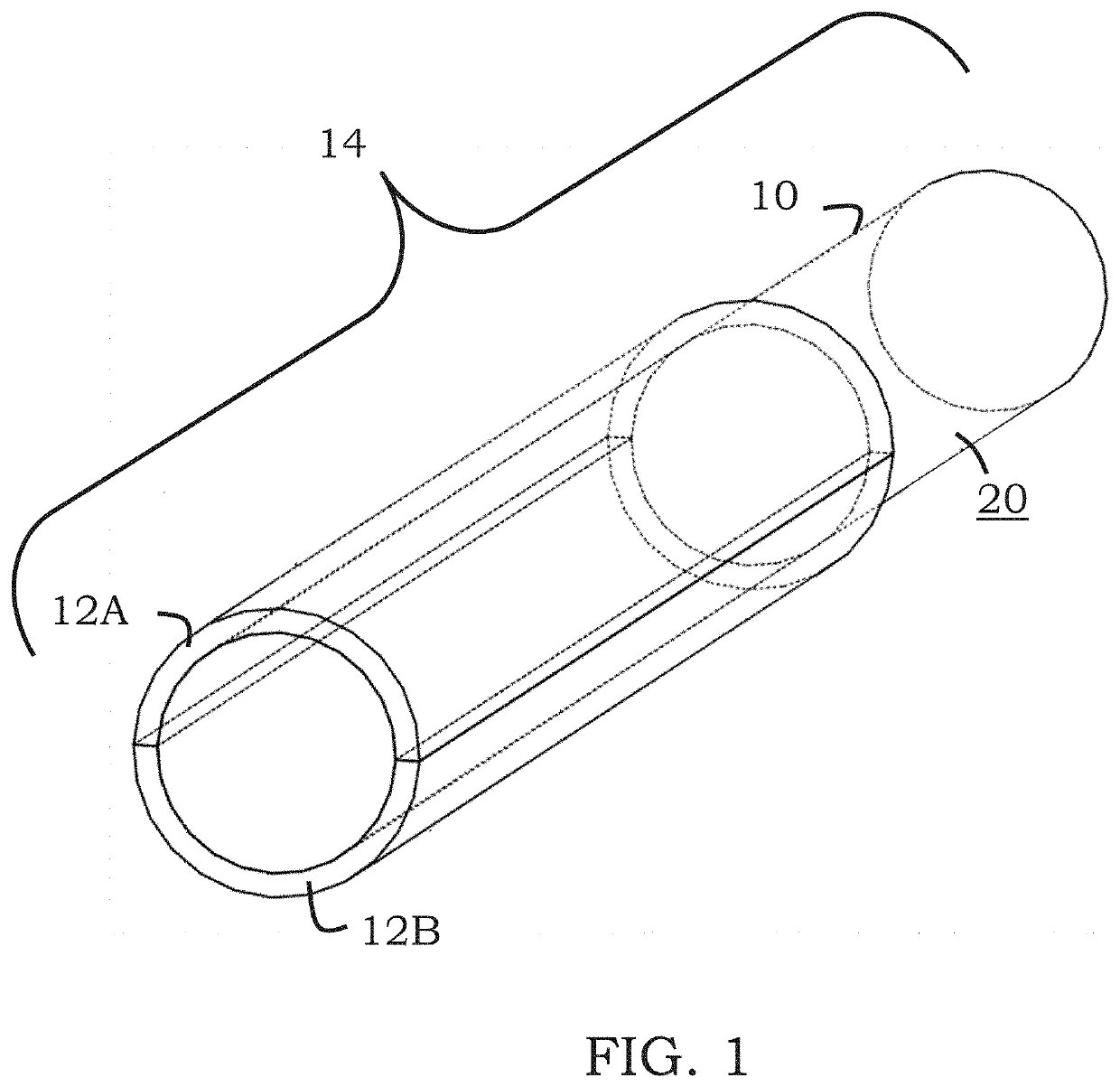
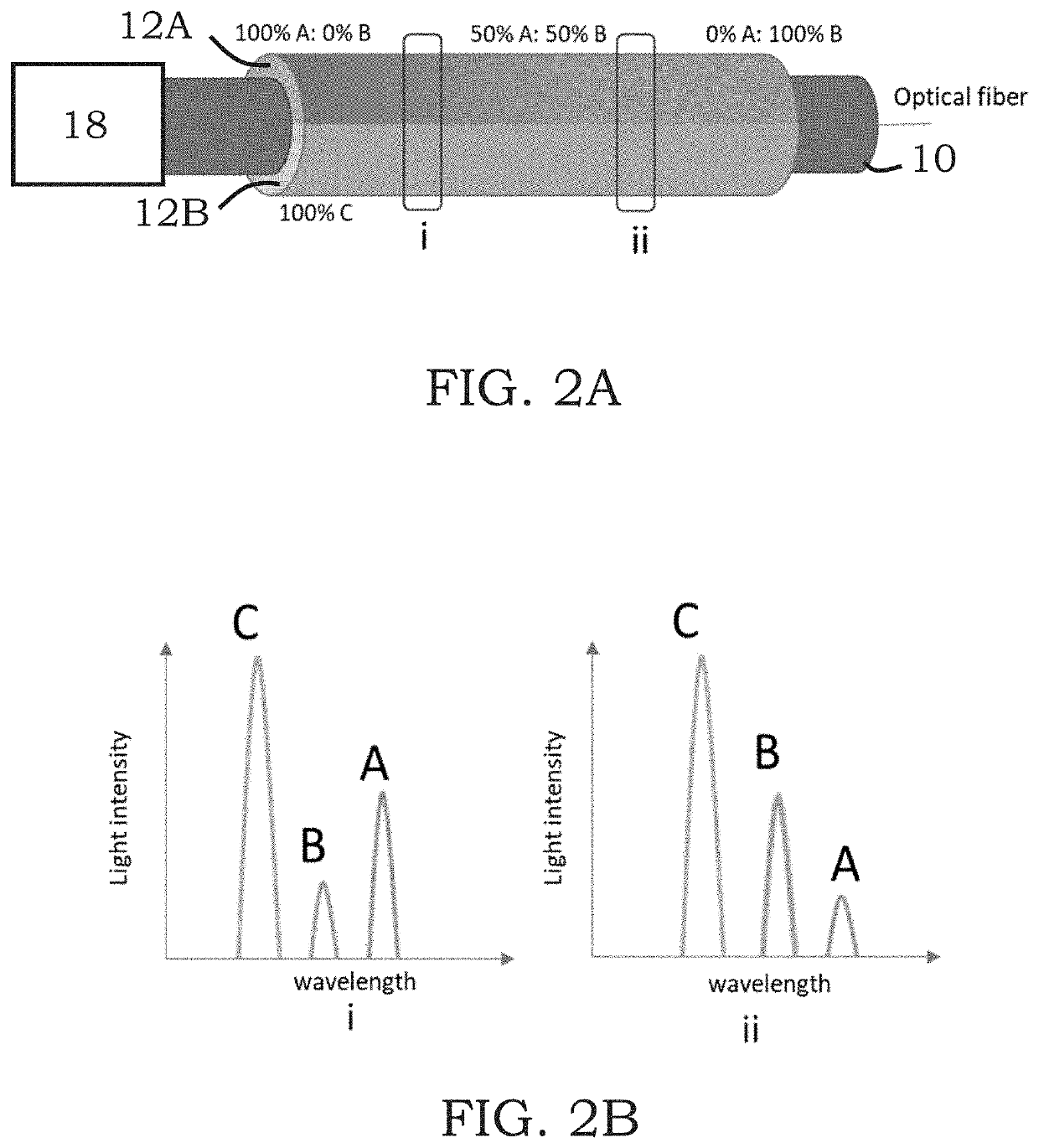
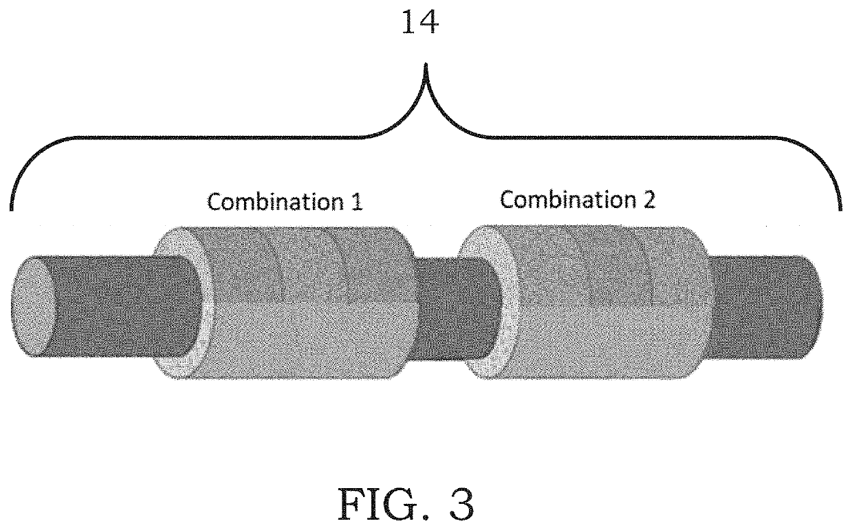
[0035]FIG. 1 depicts an optical fiber sensor for in-situ structural damage diagnosis with two or more triboluminescent materials covering outer surface 20 of optical fiber 10. Optical fiber 10 may then be embedded in target materials 16 to be structurally diagnosed. Damage to target material 16 under consideration may result in a triboluminescent emission of multiple wavelengths of triboluminescence resulting from crystal deformation or fracture.

[0036]Analysis of the triboluminescent emission provides information on the occurrence, severity, and location of damage within target material 16 in which triboluminescent sensor 14 is embedded. The use of multiple triboluminescent crystals allows the classification of the damage modes in a composite, such as compression and tension. This technology allows for real-time, distributed damage sensing and diagnosis upon the onset of barely visible damage.

[0037]Triboluminescent material 12, as depicted in FIGS. 1-4, is coated on a bare polymethy...


PUM


Abstract

Embodiments of the present invention include a system and method for detecting or sensing damage within a target material, as well as related devices. In some embodiments, a damage sensing system including a target material, an optical fiber embedded into the target material, where the optical fiber has an outer surface running the length of the optical fiber, a photosensitive receiver, and a triboluminescent coating coated on the optical fiber.

Description

CROSS-REFERENCE TO RELATED APPLICATIONS[0001]This non-provisional application is a continuation of and claims priority to Provisional Application No. 62 / 792,700 entitled “Multiple-Wavelength Triboluminescent Optical Fiber Sensor,” filed Jan. 15, 2019 by the same inventors.BACKGROUND OF THE INVENTION[0002]1. Field of the Invention[0003]This invention relates, generally, to a multiple-wavelength triboluminescent optical fiber sensor. More specifically, the invention relates to an optical fiber sensor for in-situ structural damage diagnosis.[0004]2. Brief Description of the Prior Art[0005]An indicating sensor providing a pulse of detectable light would be a useful method for verifying whether or not various internal system functions have activated, or whether or not certain parameters of an internal system have been exceeded. Events such as movement of mechanical actuators, pistons, or gears, the activation of an explosive actuator, acceleration loads such as impact events (beyond a pr...

Claims


Application Information

Patent Timeline
IPC IPC(8): G01L1/24G01N21/95G02B6/02
CPCG01L1/242G01N21/95G02B6/02052G01N2201/088G01M11/086G02B6/0003G01L1/243
Inventor DICKENS, TARIK J.JOSHI, KUNALTRAN, PHONG
Owner FLORIDA A&M UNIVERSITY
Learn More