Pop up electrical apparatus

a technology of electrical equipment and pop-up, which is applied in the direction of charging stations, coupling device connections, transportation and packaging, etc., can solve the problems of increasing equipment failure, increasing maintenance costs, and initial purchase price, and robots can be exposed to accidental damage, difficult and impractical,

Active Publication Date: 2022-10-25
KAUFFMANN ALAN
View PDF19 Cites 0 Cited by
  • Summary
  • Abstract
  • Description
  • Claims
  • Application Information

AI Technical Summary

Benefits of technology

[0010]Provided in this disclosure is a charging station positioned below a horizontal surface, specifically a parking surface that hides and secures the EVSE, making it environmentally friendly and safe from damage caused accidentally or by vandalism. Instead of the connector being plugged in by the driver to the side, front, or rear of the vehicle, the present charging station robotically autonomously plugs in a primary connector from an enclosure below the ground to a secondary connector installed in the bottom of the vehicle. This design is compatible with existing technology as well as any technology that might be developed in the future. In this manner, the present charging station offers convenience of driving a vehicle over the top of the charging station where the station plugs in the connector automatically for the driver, at home as well as away from home.
[0013]The secondary connector includes a housing and substrate that mounts in the chassis of the vehicle having a bottom flush with the bottom surface of the chassis. Within the housing is an inverted cone shaped component that serves as a mounting surface for the secondary connector and is inserted in such a way that it floats freely within the substrate. The floating mount floats inside the substrate so that the inverted cone freely moves horizontally in all directions from the center to achieve a final alignment of the primary and secondary connectors. This floating mount can “clock” or rotate several degrees to the left or right of center to enable the secondary connector to receive a primary connector that is several inches off-center. In this way, the floating mount can accommodate a vehicle that is not perfectly aligned in a parking space.
[0020]According to another aspect of the invention, a reduced number of elements and a reduced number of steps are provided to plug in the connector to an electric vehicle.
[0022]According to still another aspect of the invention, a system is provided that is easy to manufacture, install, and maintain.

Problems solved by technology

However, such increased complexity can result in increased equipment failure, maintenance cost, and initial purchase price.
Such robots can be exposed to accidental damage, vandalism, theft, and malfunction, further contributing to cost
This type of device is relatively simple compared to an above ground robot but are known to be prone to certain concerns that has prevented them from gaining acceptance within the industry.
Moreover, below-ground charging devices require the vehicle to be parked precisely over the primary connector for the connection to be made, which was difficult and impractical.
Precise alignment between the primary and secondary connectors can be achievable, though this arrangement is difficult to seal the enclosure from moisture.
This tilting beam suffers from the same difficulties as the linear rails in that it is difficult to seal the enclosure and components against moisture.
However, induction charging is not practical for commercial use.
Induction charging is only approved for up to 11 KW at the present time and will never be capable of DC fast charging, and so several hours of charging are required to gain any significant driving range.
However, there are similar concerns for an in-ground, flush-mounted charging station that plugs into the bottom of an electric vehicle as for commercial, above-ground charging stations with 20 foot cables with a connector on the end, since both types of EVSEs are exposed to the same environment.

Method used


Image

  • Pop up electrical apparatus
  • Pop up electrical apparatus
  • Pop up electrical apparatus

Examples


Embodiment Construction

[0030]Referring now to the drawings wherein the showings are for purposes of illustrating embodiments of the article only and not for purposes of limiting the same, and wherein like reference numerals are understood to refer to like components:

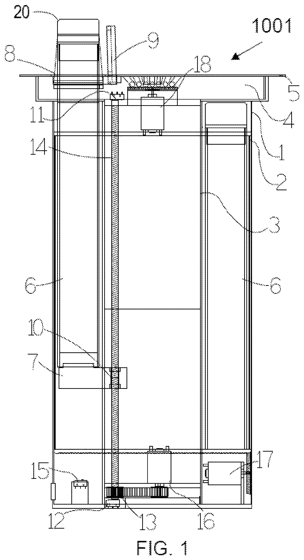
[0031]The principal objective of the present invention is to provide a more convenient method and apparatus for charging an electric vehicle that is automated, simple, reliable and inexpensive. The present invention compensates for misalignment between the primary and secondary connectors and maintains sufficient force between the connectors to keep the connectors securely connected throughout a charge cycle, while removing the driver from the job of plugging in the connector. Construction of the present invention is accomplished by means of commonly used materials and methods used in construction of such devices.

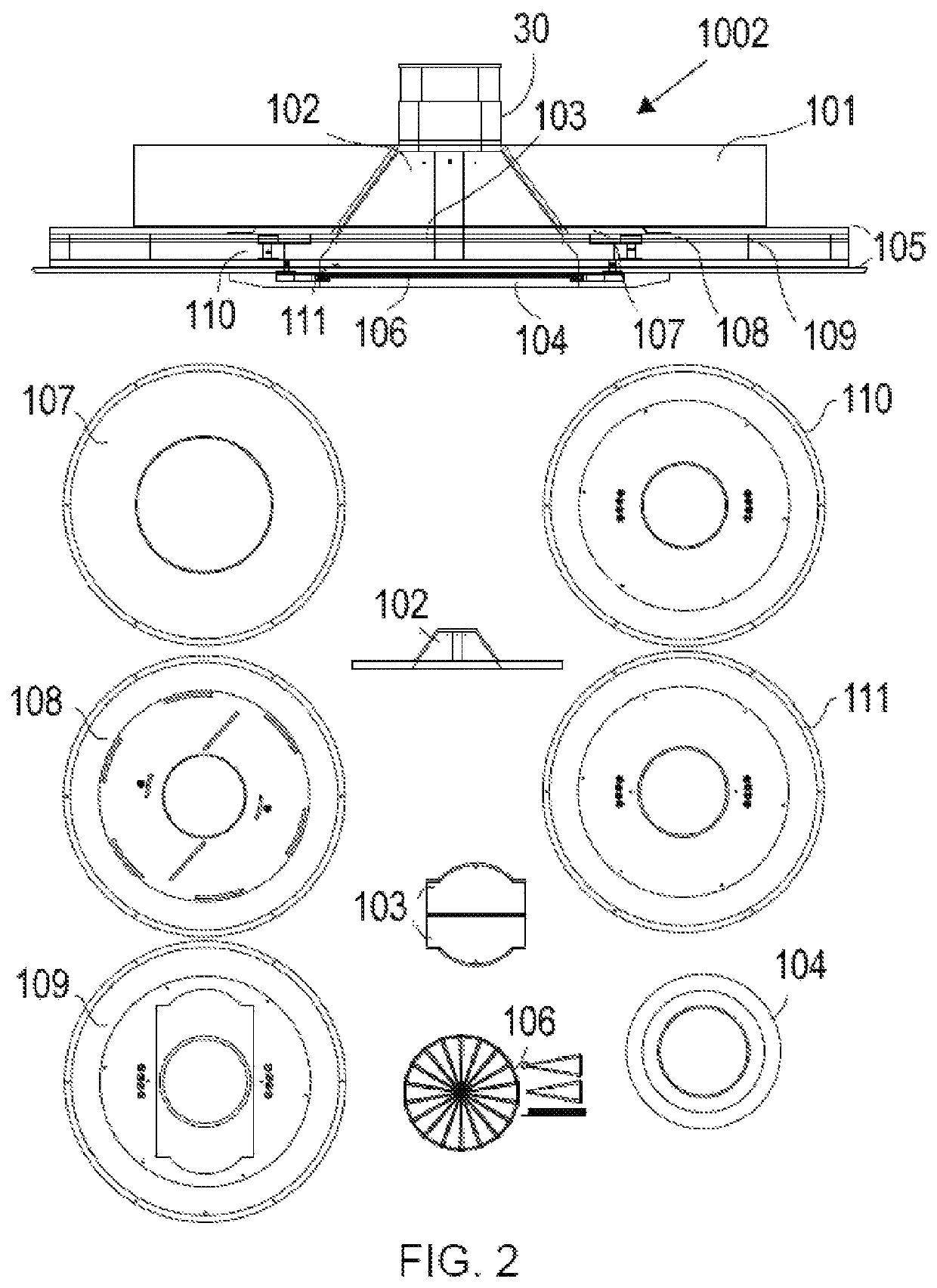
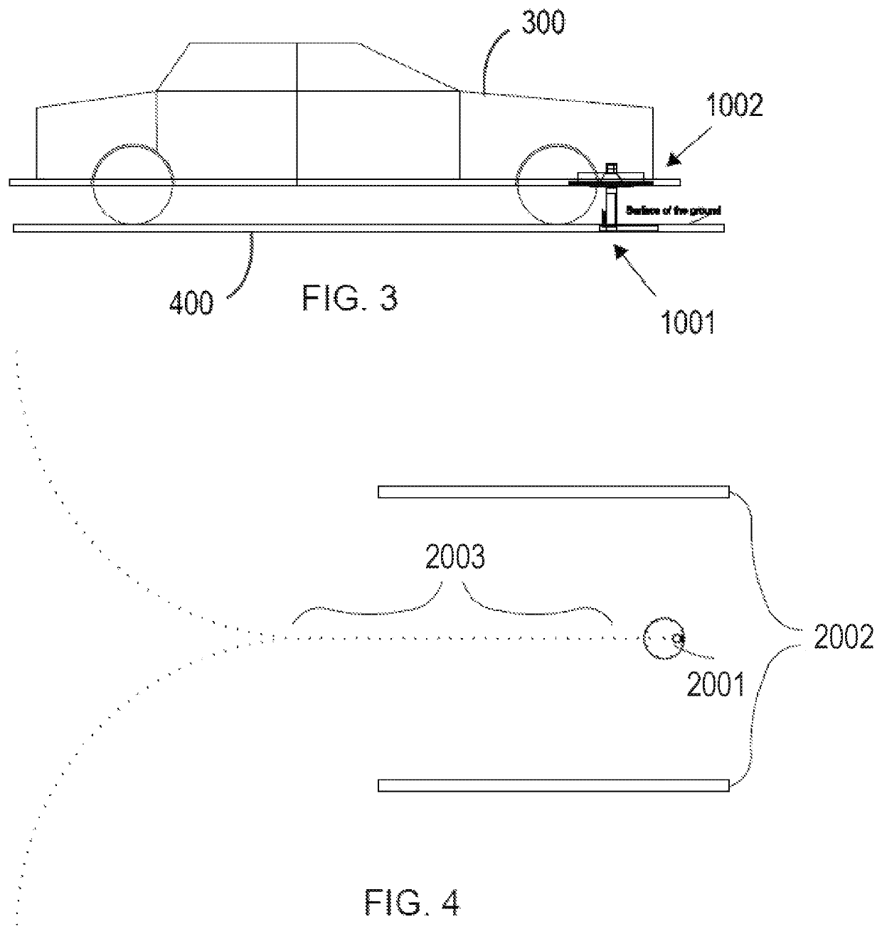
[0032]According to the present invention, an exemplary embodiment includes two principal assemblies: a primary connector 1001, as pa...


PUM


Abstract

Provided in this disclosure is a charging apparatus for an electrical vehicle. When an electric vehicle is parked above the charging apparatus, a primary connector is slide-ably extended upwards and out of an enclosure in such a manner that it plugs into a secondary connector installed in the bottom of the chassis of the vehicle. The secondary connector includes an inverted cone-shaped component that is mounted to freely move horizontally in all directions from the center to engage the slide-ably extending portion of the primary connection and thereby achieve a final alignment of the primary and secondary connectors.

Description

[0001]This application claims the benefit of U.S. Provisional Application No. 62 / 777,136, entitled AN AUTOMATED UNIVERSAL POP UP APPARATUS, THAT WILL PLUG IN A PRIMARY CONNECTOR TO A SECONDARY CONNECTOR WHICH IS AFFIXED TO AN ELECTRIC VEHICLE, filed Dec. 8, 2018, which is fully incorporated herein by reference.I. BACKGROUNDA. Technical Field[0002]This invention pertains to the field of electrical connections between an electrical supply and an electric vehicle for the purpose of charging the electrical storage device of the vehicle.B. Description of Related Art[0003]An electrical supply for an electric vehicle is commonly known as a “charging station” or an EVSE (Electric Vehicle Service Equipment) that is mounted on a parking surface. The EVSE serves as the interface between the driver and the station. A cable is attached to the EVSE power supply and has a conductive connector attached to the other end which in turn is plugged into the connector that is installed on the side, rear,...

Claims


Application Information

Patent Timeline
Patent Type & Authority Patents(United States)
IPC IPC(8): B60L53/30H01R13/52B60L53/16H01R13/631
CPCB60L53/30B60L53/16H01R13/5213H01R13/631H01R2201/26H01R13/6315Y02T10/70Y02T10/7072Y02T90/14Y02T90/12
Inventor KAUFFMANN, ALAN
Owner KAUFFMANN ALAN
Why Eureka
Try Eureka