Coupling mechanism for a surgical device

a coupling mechanism and surgical device technology, applied in the field of surgical tool parts and coupling mechanisms, can solve the problems of reducing the rotational alignment of drive dog mechanisms with fewer flat surfaces, affecting the accuracy of cutting, and reducing the accuracy of cutting

Active Publication Date: 2022-10-11
ZETHON
View PDF8 Cites 0 Cited by
  • Summary
  • Abstract
  • Description
  • Claims
  • Application Information

AI Technical Summary

Benefits of technology

[0038]Driving a tool-piece via three coupling elements allows the tool-piece to be inserted into the mechanism in a greater number of rotational arrangements. This makes it easier to insert the tool-piece into the coupling mechanism. It also provides more secure driving and coupling as the driving elements secure the bur along a greater number of directions.
[0064]According to a further embodiment, the proximal end of the shaft is conical or frusto-conical. This can help to ease driving members out of the way of the tool-piece, as well as allowing the tool-piece to be easily inserted at any rotation.

Problems solved by technology

It is often necessary to replace the tool-piece after use as it may become contaminated and the cutting portion may be dulled.
Whilst a strong driving force may be provided through non-adjustable mechanisms, these mechanisms do not allow tool-pieces to be adjusted along their longitudinal length.
In addition, drive dog mechanisms with fewer flat surfaces are more difficult to align rotationally, as the number of possible alignment positions is proportional to the number of driving surfaces.
Accordingly, this type of arrangement requires a more complicated coupling mechanism (as two separate mechanisms are required).
Whilst this type of mechanism allows the bur to be adjusted longitudinally, its drive dog has only two flat surfaces, which makes it difficult to align rotationally.
In addition, the bur receives securing forces in one direction only, meaning that it is liable to jump to one side when being driven.
Whilst this type of bur may be adjusted longitudinally (via the selection of one of the grooves) and rotationally (as the surface is cylindrical), it is difficult to get sufficient torque through the drive mechanism due, in part, to the system driving via the cylindrical surface.

Method used


Image

  • Coupling mechanism for a surgical device
  • Coupling mechanism for a surgical device
  • Coupling mechanism for a surgical device

Examples


Embodiment Construction

[0067]Embodiments described herein provide a novel coupling mechanism for transmitting sufficient torque whilst allowing longitudinal adjustability in a compact footprint. This is suitable for driving any rotational tool, such as a bur or drill. Nevertheless, for simplicity, the following description shall relate to burs.

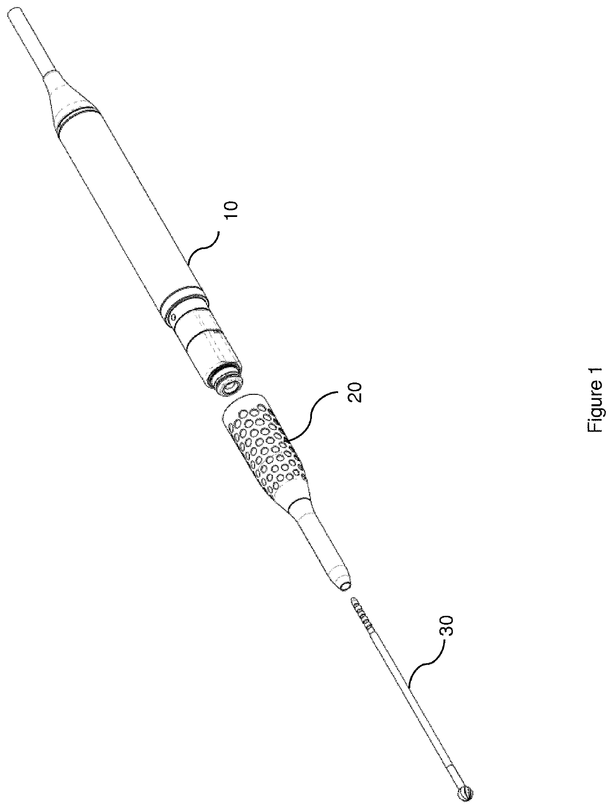
[0068]FIG. 1 shows a handpiece, nosepiece and bur according to an embodiment. The handpiece 10 comprises a coupling mechanism configured to secure and drive the bur 30. The nosepiece 20 fits over the coupling mechanism of the handpiece 10. The nosepiece 20 comprises a longitudinal channel configured to receive the bur 30 to stabilise the bur 30 as it is being driven by the handpiece 10.

[0069]In an alternative arrangement, the nosepiece 20 may provide a driving force to the bur 30. In this case, the nosepiece 20 comprises a coupling mechanism configures to secure and drive the bur 30. The nosepiece 20 in turn is coupled to the handpiece 10 that provides the driving f...


PUM


Abstract

A surgical tool-piece and a coupling mechanism for a surgical tool-piece are provided. The surgical tool-piece is configured to be driving by a driving mechanism. The surgical tool-piece comprises a shaft having a longitudinal axis running from a distal end of the shaft to a coupling portion at a proximal end of the shaft. The coupling portion comprises a driving section comprising at least three indentations located around the circumference of the coupling portion, each indentation being configured to receive a corresponding driving element of the driving mechanism to secure the tool-piece both longitudinally and rotationally.

Description

[0001]This application is a National Stage Entry of International Patent Application No. PCT / EP2018 / 062586, filed May 15, 2018, entitled “COUPLING MECHANISM FOR A SURGICAL DEVICE,” which claims priority to United Kingdom Patent Application No. 1707751.2, filed May 15, 2017, entitled “COUPLING MECHANISM FOR A SURGICAL DEVICE”, each of which is incorporated by reference herein, in the entirety and for all purposes.TECHNICAL FIELD[0002]The present disclosure relates to surgical tool-pieces and coupling mechanisms for securing surgical tool-pieces. In particular, but without limitation, this disclosure relates to surgical tools and coupling mechanisms for surgical tools.BACKGROUND[0003]During surgical procedures, it is often necessary to cut bone or other tissue. To this end, pneumatically or electrically powered surgical drills and burs may be utilised. These surgical tools often comprise a handpiece for driving a tool-piece comprising a cutting portion. The tool-piece is a cutting mea...

Claims


Application Information

Patent Timeline
Patent Type & Authority Patents(United States)
IPC IPC(8): A61B17/16A61B17/00A61C17/02B23B31/107A61C1/14
CPCA61B17/162A61B17/1633A61B17/1622A61B2017/00464A61B2017/00477A61C1/144A61C17/0202B23B31/107B23B31/1071B23B31/1072A61B17/16
Inventor DESOUTTER, WILLIAMCOURTNEY, TOBY
Owner ZETHON
Why Eureka
Try Eureka