
Personal mobility

a technology for personal mobility and grip parts, applied in the field of personal mobility, can solve the problems of limiting the transmission of vibration or shock to the grip parts, inconvenience to users, etc., and achieve the effect of reducing vibration and shock transmission

Active Publication Date: 2022-09-13
HYUNDAI MOTOR CO LTD +1
View PDF21 Cites 0 Cited by
  • Summary
  • Abstract
  • Description
  • Claims
  • Application Information

AI Technical Summary

Benefits of technology

[0005]It is an aspect of the disclosure to provide a personal mobility capable of reducing vibration and shock transmitted to opposite grip parts during driving.
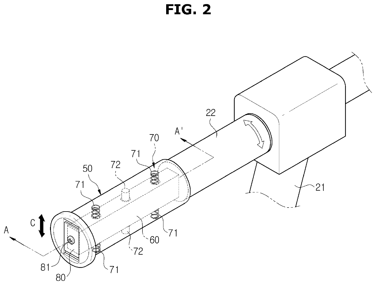
[0007]In accordance with an aspect of the disclosure, a personal mobility includes a steering shaft, a handlebar extending from an upper end of the steering shaft to opposite sides, two grip parts installed on opposite ends of the handlebar, respectively, to be displaceable with respect to the handlebar in a direction of intersecting a longitudinal direction of the handlebar, and a buffer device provided between each of the grip parts and the handlebar to reduce vibration or shock transmitted from the handlebar to the grip part.

Problems solved by technology

The personal mobility may cause inconvenience to a user because vibration or shock generated from a road surface and wheels while driving is transmitted to opposite grip parts through a steering shaft and a handlebar.
A conventional personal mobility is equipped with a shock absorber at a portion connecting a front wheel and a steering device, but there is a limit in reducing vibration or shock transmitted to the grip parts.

Method used


Image

  • Personal mobility
  • Personal mobility
  • Personal mobility

Examples


Embodiment Construction

[0022]Hereinafter, embodiments of the disclosure will be described in detail with reference to the accompanying drawings. The embodiments described below are provided by way of example so that those skilled in the art will be able to fully understand the spirit of the disclosure. The disclosure is not limited to the embodiments described below, but may be embodied in other forms. In order to clearly explain the disclosure, parts not related to the description are omitted from the drawings, and the width, length, thickness, etc. of the components may be exaggerated for convenience.

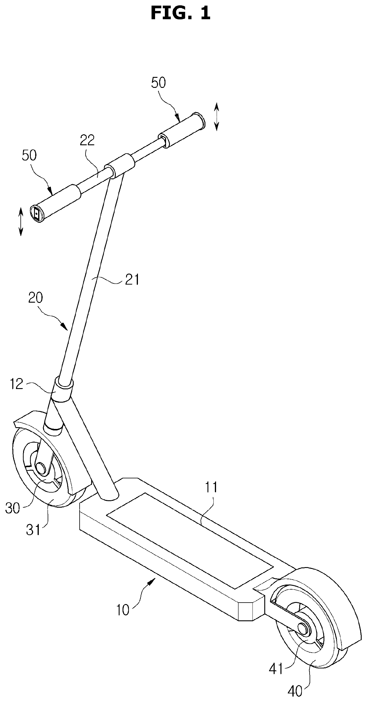
[0023]As illustrated in FIG. 1, a personal mobility according to an embodiment of the disclosure may include a main body 10 provided with a footrest 11 on an upper end thereof, a steering device 20 provided in front of the main body 10, a front wheel 30 installed at a lower end of the steering device 20, and a rear wheel 40 installed at a rear end of the main body 10.

[0024]The front wheel 30 and the rear wh...


PUM


Abstract

A personal mobility includes a steering shaft, a handlebar extending from an upper end of the steering shaft to opposite sides, two grip parts installed on opposite ends of the handlebar, respectively, to be displaceable with respect to the handlebar in a direction of intersecting a longitudinal direction of the handlebar, and a buffer device provided between each of the grip parts and the handlebar to reduce vibration or shock transmitted from the handlebar to the grip part.

Description

CROSS REFERENCE TO RELATED APPLICATIONS[0001]This application is based on and claims priority under 35 U.S.C. § 119 to Korean Patent Application No. 10-2020-0187522, filed on Dec. 30, 2020, in the Korean Intellectual Property Office, the disclosure of which is incorporated by reference herein in its entirety.BACKGROUND1. Field[0002]The disclosure relates to a personal mobility capable of reducing vibration and shock transmitted to opposite grip parts during driving.2. Description of the Related Art[0003]As used throughout this patent, the phrase “personal mobility” is intended to mean any moving personal vehicle, device, machine, instrument, apparatus, or the like. Recently, the use of a personal mobility such as an electric kickboard and an electric bicycle is expanding. The personal mobility may drive on roadways, sidewalks, narrow alleys, and the like by electric power, and may be used as a means for moving a short distance or a means for leisure.[0004]The personal mobility may c...

Claims


Application Information

Patent Timeline
Patent Type & Authority Patents(United States)
IPC IPC(8): B62K21/26B62K21/14B62K11/14B62K3/00
CPCB62K21/14B62K3/002B62K11/14B62K21/26B62K23/04F16F15/04F16F15/023F16F15/022B62K2201/04B62K2201/08
Inventor SONG, ILSUNSEOK, DONGHEEKIM, DUCK YOUNGRO, HEE JINJANG, YOCHEOL
Owner HYUNDAI MOTOR CO LTD
Learn More