Bracket assembly for a multi-link suspension system

a multi-link suspension and bracket technology, applied in the field of suspension systems, can solve the problems of limited and problematic suspension system tuneability, chassis-mounted brackets, disadvantages,

Active Publication Date: 2022-07-26
HAMMER CONCEPTS & DESIGNS LLC
View PDF28 Cites 3 Cited by
  • Summary
  • Abstract
  • Description
  • Claims
  • Application Information

AI Technical Summary

Benefits of technology

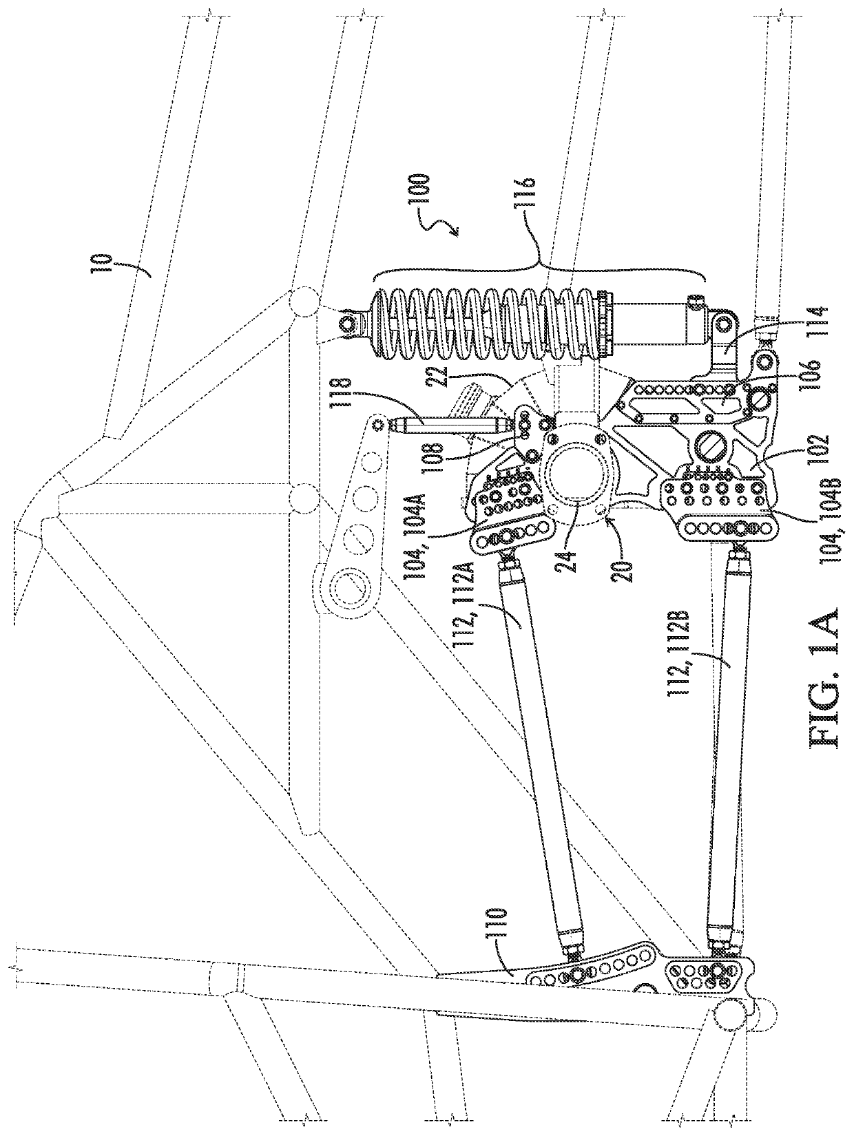
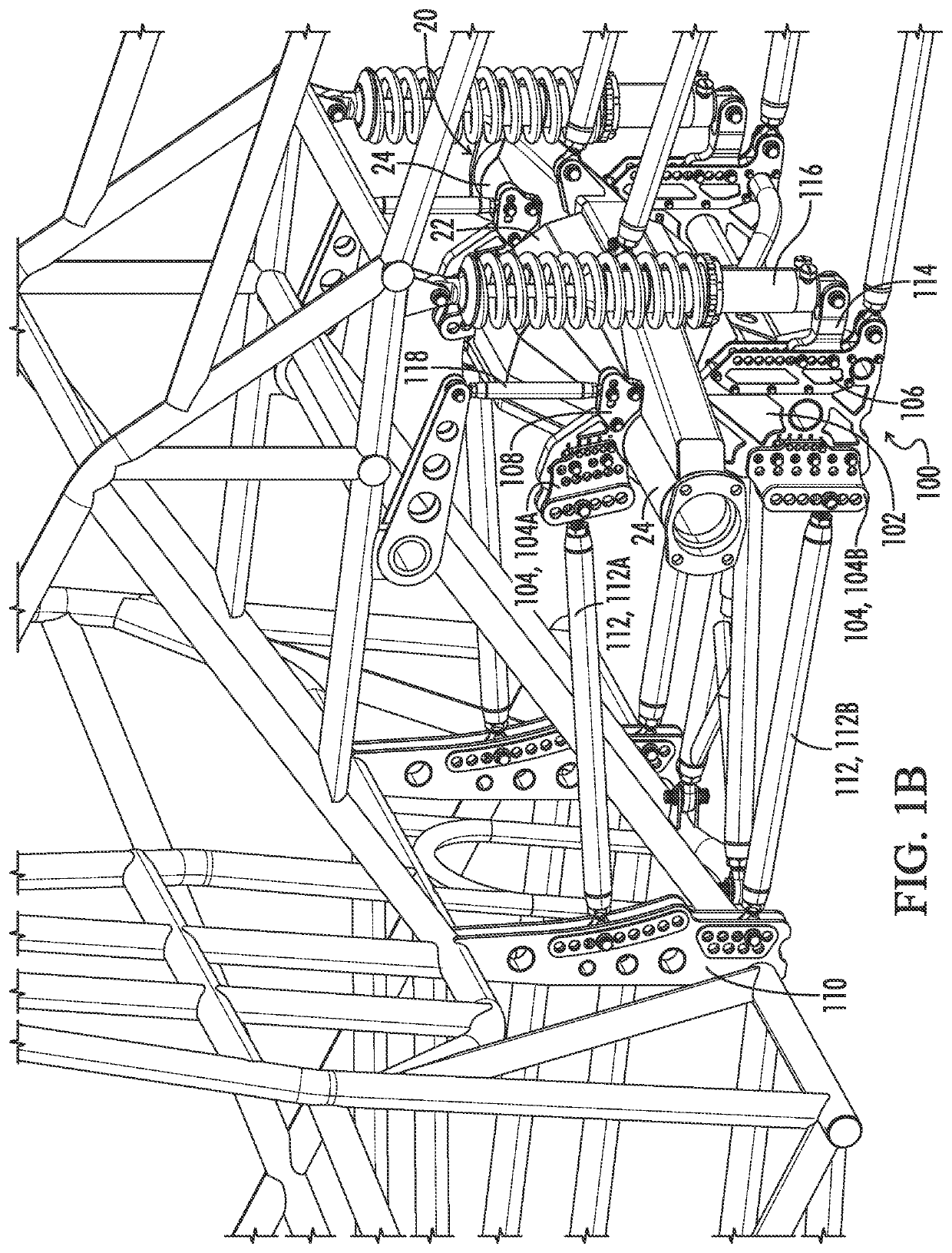
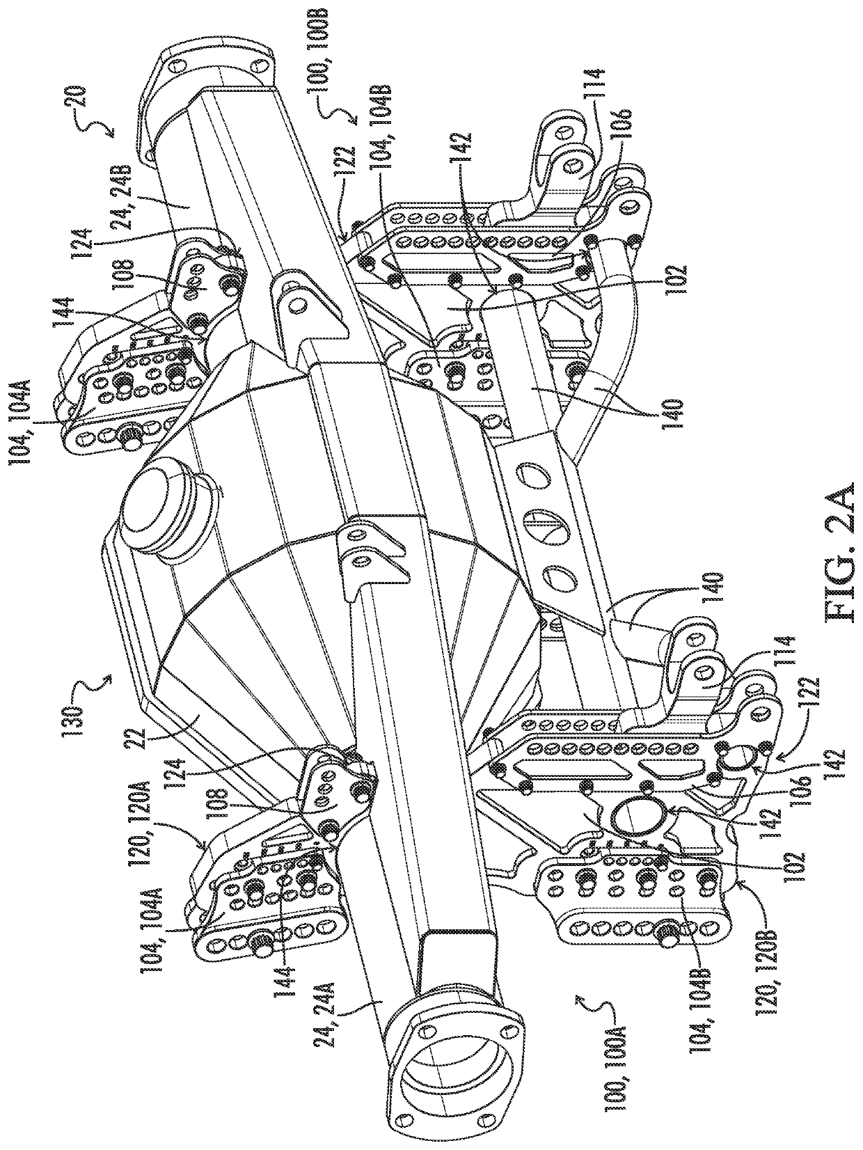
[0013]In the context of a bracket assembly for a multi-link suspension system, the current disclosure provides a bracket assembly mounted to a housing of an automotive vehicle, as opposed to a chassis, or a frame, of the automotive vehicle, enabling ease of replacement of the housing and adjustability of suspensions system components, such as at least one trailing arm, an anti-roll bar, a shock absorber coupler, or a shock absorber.
[0016]The current disclosure further provides a bracket assembly mounted to a housing of an automotive vehicle, offering adjustability of the mounting points of at least one trailing arm in steps at least as fine as one-eighth-of-an-inch (⅛″) increments. The current disclosure sets forth a bracket assembly mounted to a housing of an automotive vehicle, wherein an adjustable shock absorber coupler may be adjusted in steps at least as fine one-half-of-an-inch (½″) increments. The current disclosure sets forth a bracket assembly mounted to a housing of an automotive vehicle, wherein an anti-roll bar may be adjusted in steps at least as fine as one-half-of-an-inch (½″) increments.

Problems solved by technology

While current suspension systems provide the foregoing advantages, they are still limited and problematic.
While the latter permits some degree of configuration, the tuneability of a suspension system is limited by steps of sizeable increments.
Chassis-mounted brackets, however, are disadvantageous for a number of reasons.
Chassis-mounted bracket assemblies are limited insofar as they only provide instant center adjustability, due to the configuration of the mounting points for trailing arms.
This is particularly problematic as chassis-mounted bracket assemblies are often fixedly installed on the frame of the vehicle, such that the chassis-mounted bracket cannot be positionally relocated for change of instant center points along and across the mounting points for the trailing arms on the chassis-mounted bracket.
Another drawback associated with chassis-mounted bracket assemblies is that the chassis-mounted bracket assemblies often installed on the frame of the vehicle, leaving the chassis-mounted bracket assemblies to remain on the vehicle for the remainder of frame's life, unless and until the chassis of the vehicle is re-manufactured or otherwise reconstructed.
This is particularly detrimental for vehicles utilized for high-performance applications, such as drag-racing vehicles, where the tunability or adjustability of an instant center point may need to be changed or altered prior to, or during, a race or performance of the vehicle having the chassis-mounted bracket assembly.
In addition to the limitation as to adjustability and tunability, chassis-mounted bracket assemblies are strictly limited to the configuration, or reconfiguration, of mounting points for trailing arms.
Chassis-mounted bracket assemblies provide no additional adjustability as it relates to other components in a vehicle's suspension system, including such components as anti-roll bars, shock mounts, and shock absorbers.
As such, a chassis-mounted bracket assembly lacks versatility in a suspension system, which is needed within the industry of suspension systems for vehicles, particularly those utilized for high-performance applications, such as drag-racing.

Method used


Image

  • Bracket assembly for a multi-link suspension system
  • Bracket assembly for a multi-link suspension system
  • Bracket assembly for a multi-link suspension system

Examples


Embodiment Construction

[0066]Reference will now be made in detail to embodiments of the present disclosure, one or more drawings of which are set forth herein. Each drawing is provided by way of explanation of the present disclosure and is not a limitation. In fact, it will be apparent to those skilled in the art that various modifications and variations can be made to the teachings of the present disclosure without departing from the scope of the disclosure. For instance, features illustrated or described as part of one embodiment can be used with another embodiment to yield a still further embodiment.

[0067]Thus, it is intended that the present disclosure covers such modifications and variations as come within the scope of the appended claims and their equivalents. Other objects, features, and aspects of the present disclosure are disclosed in, or are obvious from, the following detailed description. It is to be understood by one of ordinary skill in the art that the present discussion is a description o...


PUM


Abstract

A bracket assembly for a multi-link suspension system is provided, said bracket assembly mounted to a housing of an automotive vehicle, as opposed to a chassis of the automotive vehicle, enabling modularity and ease of replacement of the housing and adjustability of suspensions system components. The bracket assembly may have a body, wherein the body includes: an axle tube hole; one or more cross tube support holes; at least one trailing arm attachment portion having a first plurality of adjustment holes and a second plurality of adjustment holes; an anti-roll bar attachment portion having one or more attachment holes; and a shock attachment portion having a plurality of attachment holes. Further, the bracket assembly may include one or more engagement points, configured to support a number of said suspension system components, such as at least one trailing arm, an anti-roll bar, a shock absorber coupler, and a shock absorber.

Description

CROSS-REFERENCES TO RELATED APPLICATIONS[0001]A portion of the disclosure of this patent document contains material that is subject to copyright protection. The copyright owner has no objection to the reproduction of the patent document or the patent disclosure, as it appears in the U.S. Patent and Trademark Office patent file or records, but otherwise reserves all copyright rights whatsoever.FIELD OF THE DISCLOSURE[0002]The present disclosure relates generally to a suspension system, and more particularly to an adjustable bracket assembly for a multi-link suspension system for an automotive vehicle.BACKGROUND[0003]Within the automotive industry, and especially within the automotive racing industry, there are a number of suspension systems that are utilized. These suspension systems include, but are not limited to, four-link suspension systems, three-link suspension systems, and ladder-bar suspension systems. A suspension system, whether it is a four-link suspension system, a three-...

Claims


Application Information

Patent Timeline
Patent Type & Authority Patents(United States)
IPC IPC(8): B60G7/00
CPCB60G7/001B60G7/008B60G7/02B60G21/055B60G9/022B60G2204/61B60G2200/314B60G2300/07
Inventor HAMM, BRIAN
Owner HAMMER CONCEPTS & DESIGNS LLC
Why Eureka
Try Eureka