
Fluid pressure-feed device

a fluid pressure-feed device and fluid-feeding technology, which is applied in the direction of liquid transfer devices, machines/engines, and positive-displacement liquid engines, etc., can solve the problems of large size of fluid-feed devices and difficulty in reducing the installation space of fluid-feed devices

Active Publication Date: 2022-07-05
TOYOTA JIDOSHA KK +1
View PDF18 Cites 0 Cited by
  • Summary
  • Abstract
  • Description
  • Claims
  • Application Information

AI Technical Summary

Benefits of technology

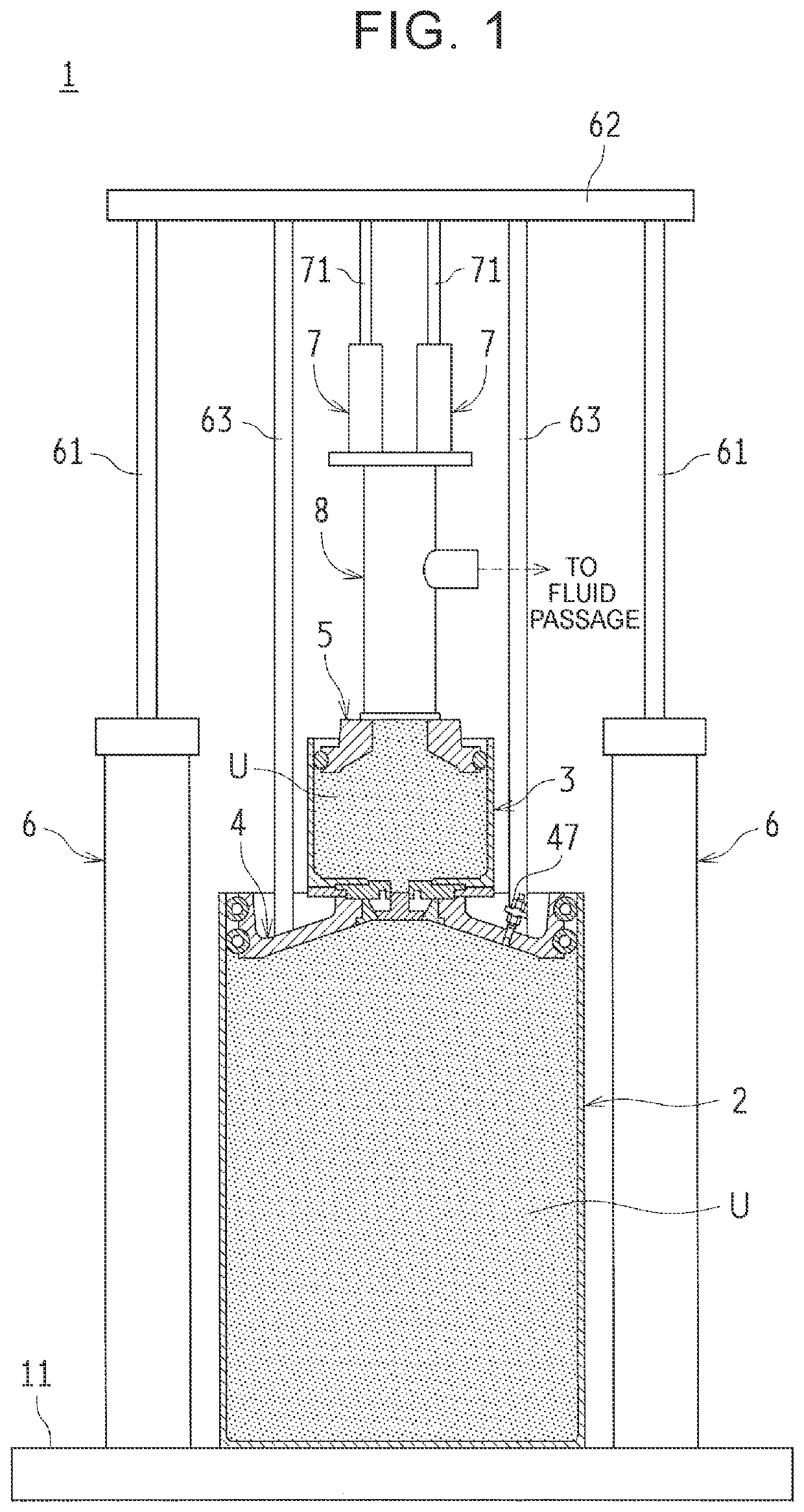
[0011]With the configuration, in a state where a sufficient amount of the fluid remains in the main tank, the fluid extruded from the main tank flows into the sub tank. The fluid inside the sub tank is then fed under pressure by the pump toward the fluid passage. Once the amount of the fluid remaining in the main tank becomes small, and the main tank needs to be replaced, it is possible to feed the fluid inside the sub tank under pressure toward the fluid passage during the replacement operation of the main tank. This means that the fluid inside the sub tank is fed under pressure by the pump toward the fluid passage. During the replacement operation, since the fluid does not flow into (is not supplied in) the sub tank, an amount of the fluid remaining in the sub tank is reduced gradually. However, when the replacement operation of the main tank is completed before the fluid inside the sub tank is gone, the fluid is forced out from the main tank again, and flows into the sub tank, and the fluid is supplied in the sub tank. Therefore, it is possible to continuously feed the fluid under pressure toward the fluid passage. It is only necessary to ensure that a capacity of the sub tank is an amount of the fluid required during replacement of the main tank (a required amount of the fluid to be fed under pressure to the fluid passage). Therefore, with the solution, it is not necessary to provide a plurality of pump units having the same configuration side by side (each unit being made of a tank and a follower plate), and it is thus possible to reduce a size of the fluid pressure-feed device.
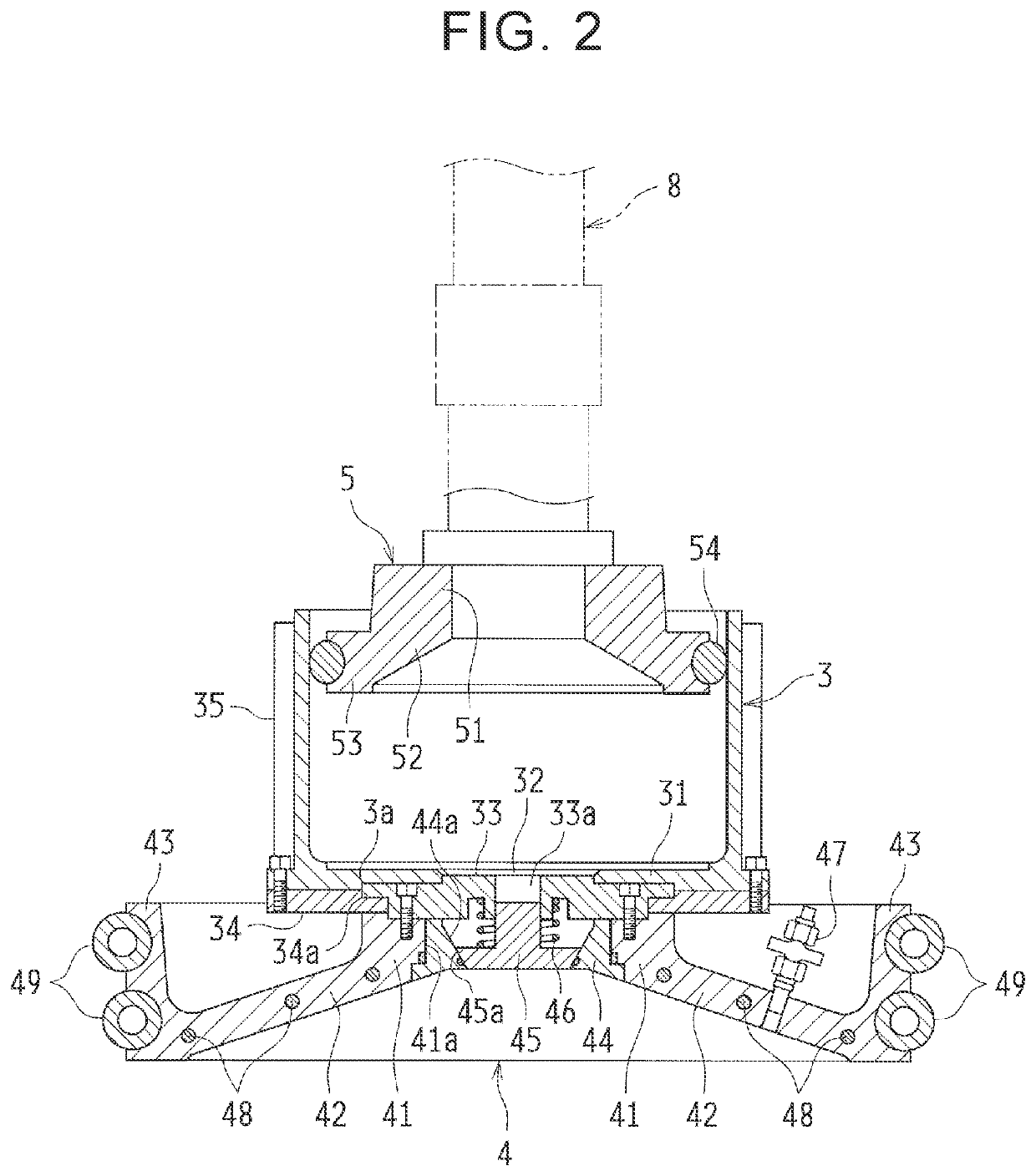
[0015]With the configuration, the check valve opens only when pressure of the fluid inside the main tank reaches the given value or higher, and the fluid flows from the main tank to the sub tank. This means that no backflow of the fluid from the sub tank to the main tank happens. Therefore, a situation is prevented where an amount of the fluid remaining in the sub tank is insufficient at a point when the main tank needs to be replaced. As a result, it is possible to avoid a situation where an amount of the fluid inside the sub tank is insufficient during the replacement operation of the main tank, and it is thus possible to continuously feed the fluid under pressure toward the fluid passage.
[0017]With the configuration, it is possible to reduce the size of the sub tank to an almost minimum, and this contributes to a size reduction of the fluid pressure-feed device.
[0018]In the disclosure, the main follower plate and the sub tank are provided. The main follower plate applies pressurizing force to the fluid inside the main tank. The sub tank is provided integrally with the main follower plate, and the fluid forced out from the main tank flows into the sub tank. Thus, the fluid is fed under pressure toward the fluid passage from the sub tank. Thus, it is possible to feed the fluid inside the sub tank under pressure to the fluid passage during the replacement operation of the main tank, and it is not necessary to provide a plurality of pump units having the same configuration. As a result, it is possible to reduce the size of the fluid pressure-feed device while enabling the fluid to be continuously fed under pressure to the fluid passage.

Problems solved by technology

However, with the configuration described in JP 2006-322359 A, since the two pump units a1, a2 are provided side by side, the size of the fluid pressure-feed device becomes large, and it is thus difficult to reduce an installation space for the fluid pressure-feed device.

Method used


Image

  • Fluid pressure-feed device
  • Fluid pressure-feed device
  • Fluid pressure-feed device

Examples


Embodiment Construction

[0027]An embodiment of the disclosure is described below based on the drawings. In the embodiment, the disclosure is applied to a fluid pressure-feed device in a vehicle body manufacturing line. The fluid pressure-feed device feeds a urethane adhesive under pressure to a coating robot. The urethane adhesive is to be applied to a window glass that is a workpiece (an adhesive for adhering the window glass to a vehicle body; a fluid).

[0028]Configuration of Fluid Pressure-Feed Device

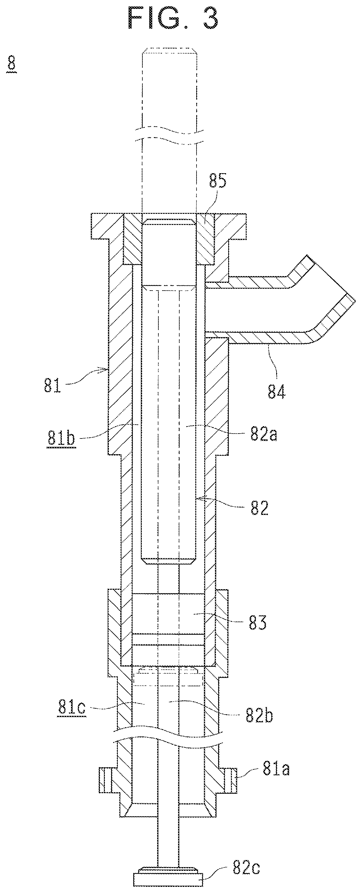
[0029]FIG. 1 is a sectional view of a part of a fluid pressure-feed device 1 according to the embodiment. As shown in the drawing, the fluid pressure-feed device 1 includes a main tank 2, a sub tank 3, a main follower plate 4, a sub follower plate 5, a pair of main cylinders 6, sub cylinders 7, a drum pump (pump) 8, and so on.

[0030]A pressure-feed operation of the urethane adhesive U in the fluid pressure-feed device 1 is roughly described as follows. As shown in FIG. 1, in a state where the main tank 2 and ...


PUM


Abstract

A fluid pressure-feed device includes a main tank and a sub tank. The sub tank is connected integrally with an upper portion of a main follower plate that applies pressurizing force to a urethane adhesive inside the main tank. A drum pump is provided in an upper portion of a sub follower plate provided in the sub tank. While the urethane adhesive is flowing into the sub tank from the main tank, the urethane adhesive is fed under pressure from the sub tank to a fluid passage by actuation of the drum pump. While the main tank is being replaced, the urethane adhesive inside the sub tank is fed under pressure to the fluid passage by the drum pump.

Description

INCORPORATION BY REFERENCE[0001]The disclosure of Japanese Patent Application No. 2018-075889 filed on Apr. 11, 2018 including the specification, drawings and abstract is incorporated herein by reference in its entirety.BACKGROUND1. Technical Field[0002]The disclosure relates to a fluid pressure-feed device that feeds a fluid such as an adhesive under pressure toward a workpiece in a vehicle body manufacturing line and the like. The disclosure relates to, for example, a measure to reduce a size of the fluid pressure-feed device.2. Description of Related Art[0003]As disclosed in Japanese Unexamined Patent Application Publication No. 2006-322359 (JP 2006-322359 A), a fluid pressure-feed device is known. The fluid pressure-feed device forces out a fluid such as an adhesive from a tank (a drum) and feeds the fluid under pressure toward a workpiece in order to apply the fluid to the workpiece in a vehicle body manufacturing line.[0004]This kind of fluid pressure-feed device includes a pu...

Claims


Application Information

Patent Timeline
Patent Type & Authority Patents(United States)
IPC IPC(8): B67D7/02B05D7/14F04B15/02B05B9/047B05C1/02
CPCB67D7/0227B05B9/047B05C1/02B05D7/14F04B15/02B05C11/10B05C11/1047B05C11/101B05C11/11B05C11/1042B67D7/645
Inventor TASAKA, MASAHIROMAKINO, RIKIYASUZUKIURASHI, TAKATOSHISUZUKI, SHOUJI
Owner TOYOTA JIDOSHA KK
Learn More