
Continuous wave radar system

Active Publication Date: 2022-06-28
NAT CHUNG SHAN INST SCI & TECH
View PDF8 Cites 0 Cited by
  • Summary
  • Abstract
  • Description
  • Claims
  • Application Information

AI Technical Summary

Benefits of technology

The patent is about a continuous wave radar system that has a device that reduces signal leakage between the transmitter and receiver without adding much extra complexity or size to the system. This device uses multiple metal plates to effectively block the leakage signal. The technical effect of this invention is a more reliable and accurate continuous wave radar system.

Problems solved by technology

Signal leakage between a transmitter and a receiver has been a challenge for designing a continuous wave radar system.
However, lengthening distance can significantly increase the overall size, and shielding can significantly increase the overall weight of the continuous wave radar system.
In order to include the signal cancellation circuit, overall circuitry of the continuous wave radar system becomes more complicated, therefore increasing design and manufacturing costs of the continuous wave radar system.

Method used


Image

  • Continuous wave radar system
  • Continuous wave radar system
  • Continuous wave radar system

Examples


Embodiment Construction

[0047]The present invention will now be described more fully hereinafter with reference to the accompanying drawings illustrating various exemplary embodiments of the invention. The present invention may, however, be embodied in many different forms and should not be construed as limited to the embodiments set forth herein. Rather, these embodiments are provided so that this disclosure will be thorough and complete, and will fully convey the scope of the disclosure to those skilled in the art. Like reference numerals refer to like elements throughout.

[0048]The terminology used herein is for the purpose of describing particular embodiments only and is not intended to be limiting of the disclosure. As used herein, the singular forms “a”, “an” and “the” are intended to include the plural forms as well, unless the context clearly indicates otherwise. It will be further understood that the terms “comprises” and / or “comprising,” or “includes” and / or “including” or “has” and / or “having” wh...


PUM


Abstract

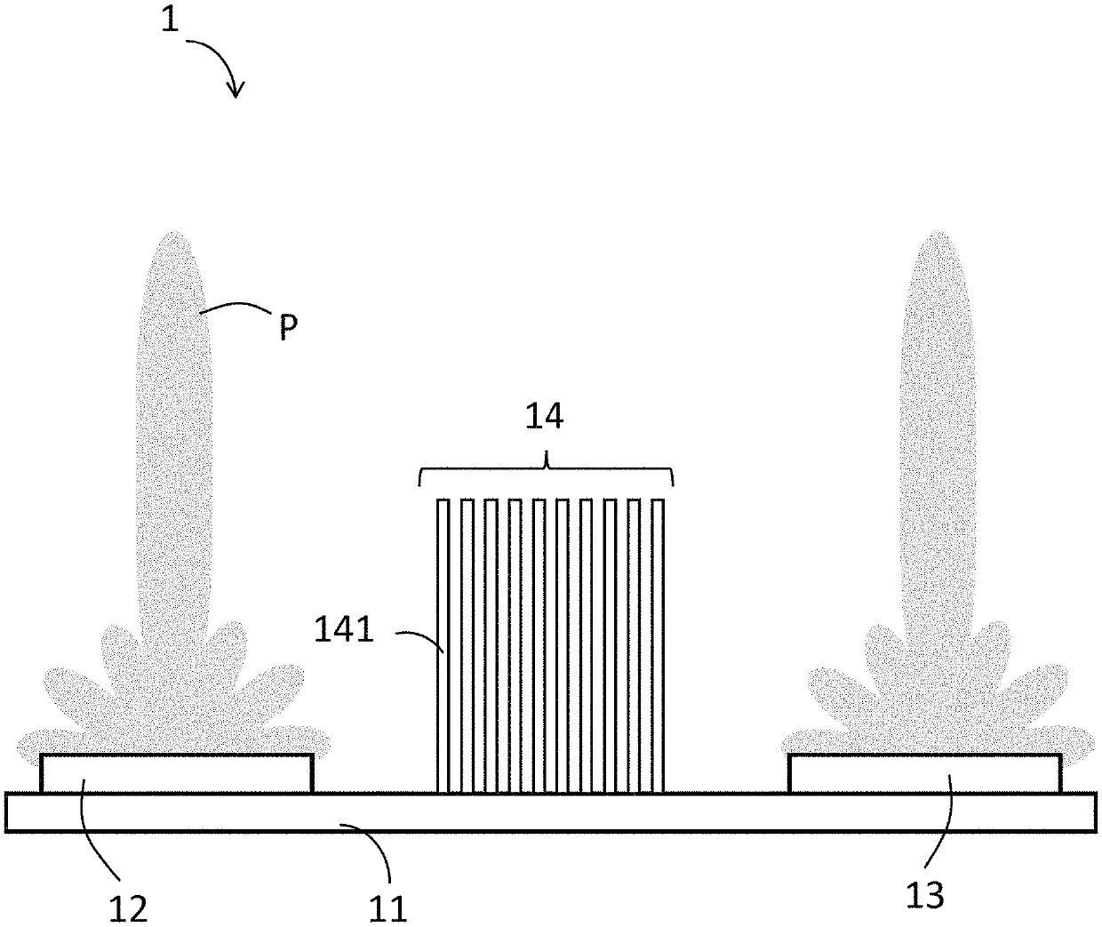
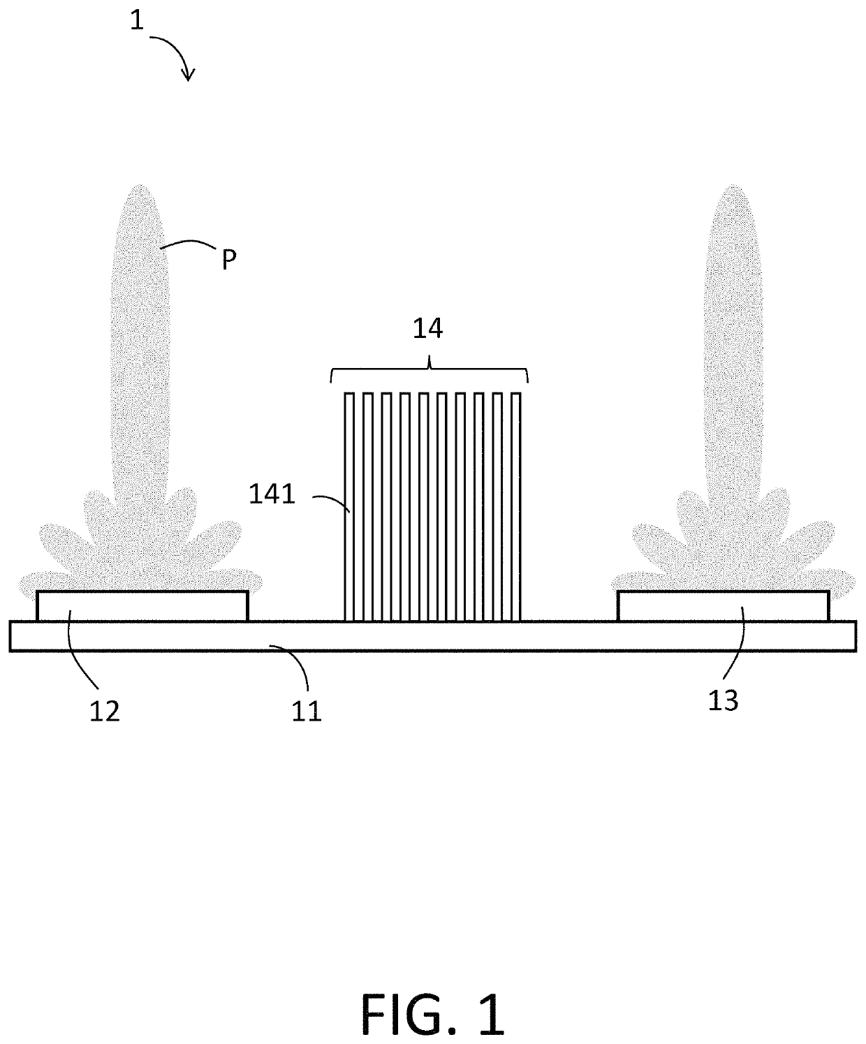
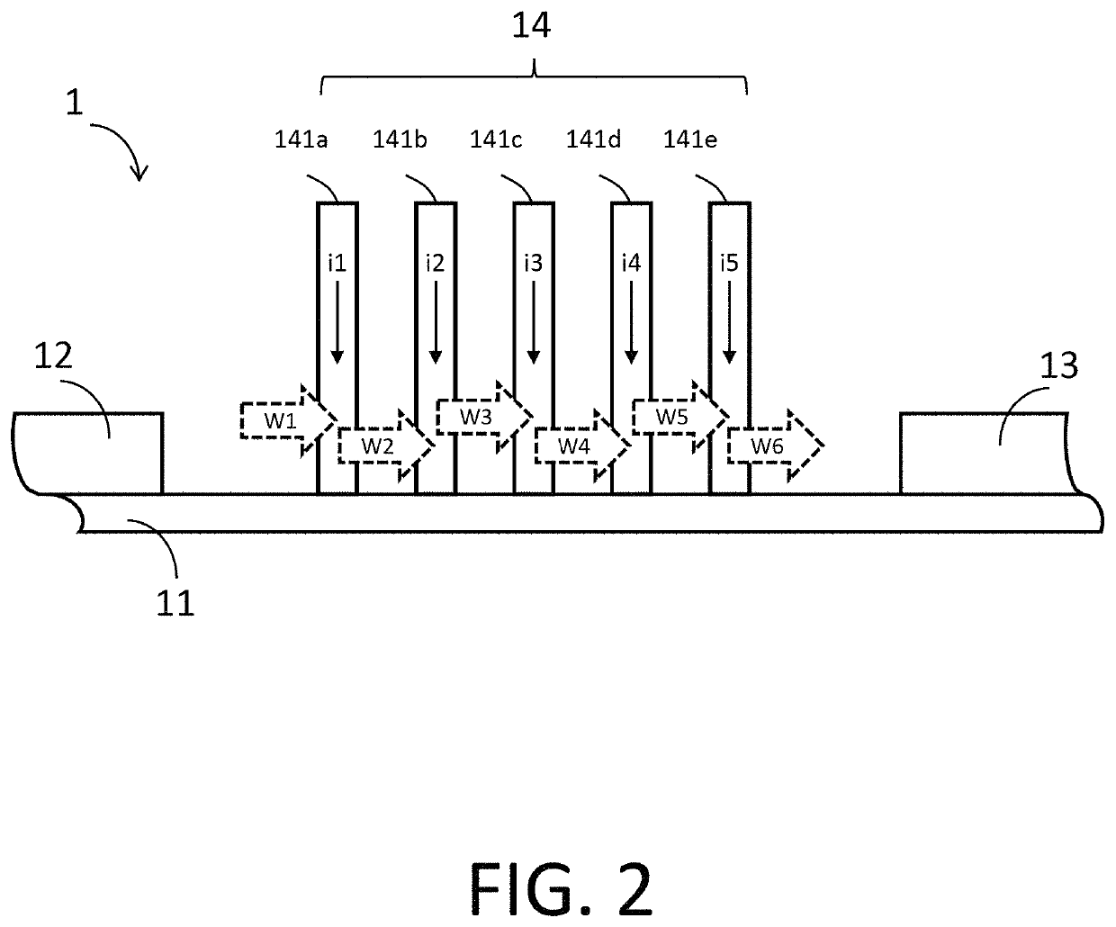
A continuous wave radar system comprises a substrate, a transmitter disposed on the substrate, a receiver disposed on the substrate, and an isolating device comprising a plurality of metal plates parallelly disposed on the substrate between the transmitter and the receiver for isolating leakage signal transmitted from the transmitter to the receiver. The metal plates are grounded with the transmitter and the receiver via electrical connection between the metal plates and the substrate. The metal plates are so arranged that an eddy current induced in each of the metal plates is directed away by grounding when the leakage signal passes through the metal plates.

Description

FIELD OF THE INVENTION[0001]The present disclosure relates to a continuous wave radar system, and more particularly, to a continuous wave radar system having an isolating device for attenuating leakage signals.BACKGROUND[0002]Signal leakage between a transmitter and a receiver has been a challenge for designing a continuous wave radar system. Traditionally, adopting physical separation, such as lengthened distance or shielding, between the receiver and the transmitter has been a common solution to reduce the signal leakage. However, lengthening distance can significantly increase the overall size, and shielding can significantly increase the overall weight of the continuous wave radar system.[0003]Another common solution to signal leakage has been to include a signal cancellation circuit in the continuous wave radar system. The signal cancellation circuit is coupled to the receiver for providing cancellation signals that cancel leakage signals from the transmitter. In order to inclu...

Claims


Application Information

Patent Timeline
IPC IPC(8): G01S7/03G01S7/35
CPCG01S7/038G01S7/35G01S7/032
Inventor TSAI, SHIH-CHECHEN, JER-LONGLIN, MIN-CHINGWANG, RUEI-SHENWEI, YOU-HENG
Owner NAT CHUNG SHAN INST SCI & TECH
Learn More