Protective covering

a protective cover and cover technology, applied in the direction of belt/chain/gearing, yielding coupling, gearbox, etc., can solve the problems of damage to the gearbox, and achieve the effect of easy production and cost-effective assembly of the protective cover

Active Publication Date: 2022-06-21
MAGNA POWERTRAIN AG & CO KG
View PDF17 Cites 0 Cited by
  • Summary
  • Abstract
  • Description
  • Claims
  • Application Information

AI Technical Summary

Benefits of technology

[0009]It is an object of the invention to specify a protective covering for a shaft output of a transfer gearbox, which effectively prevents the ingress of water into the transfer gearbox and can be manufactured and assembled cost-effectively. A further object is to specify a transfer gearbox, comprising a shaft output and a protective covering for the shaft output, with the stated advantages.
[0012]The structure made from a solid, inelastic material makes it possible to produce and assemble the protective covering easily and cost-effectively. The configuration according to the invention does not make it possible to completely prevent an ingress of water into the interior of the protective covering; however, an outflow opening is formed at the bottom of the protective covering such that water penetrating into the protective covering can flow out downwardly via the outflow opening before it ingresses into the transfer gearbox.
[0013]In the region of the second opening, a peripheral portion of the protective covering body is preferably formed such that it surrounds the shaft in a non-sealing manner, such that a gap is formed at least in certain portions between the peripheral portion of the protective covering body and the shaft. The gap is particularly preferably formed around the full periphery between the peripheral portion of the protective covering body and the shaft. By way of such a gap between the protective covering body and the shaft, the shaft can rotate freely, without grinding losses. Penetrating water can be discharged again via the outflow opening.

Problems solved by technology

Such shaft outputs of a transfer gearbox have the problem that, for example, water or dirt could penetrate into the transfer gearbox and may damage the gearbox.

Method used


Image

  • Protective covering
  • Protective covering
  • Protective covering

Examples


Embodiment Construction

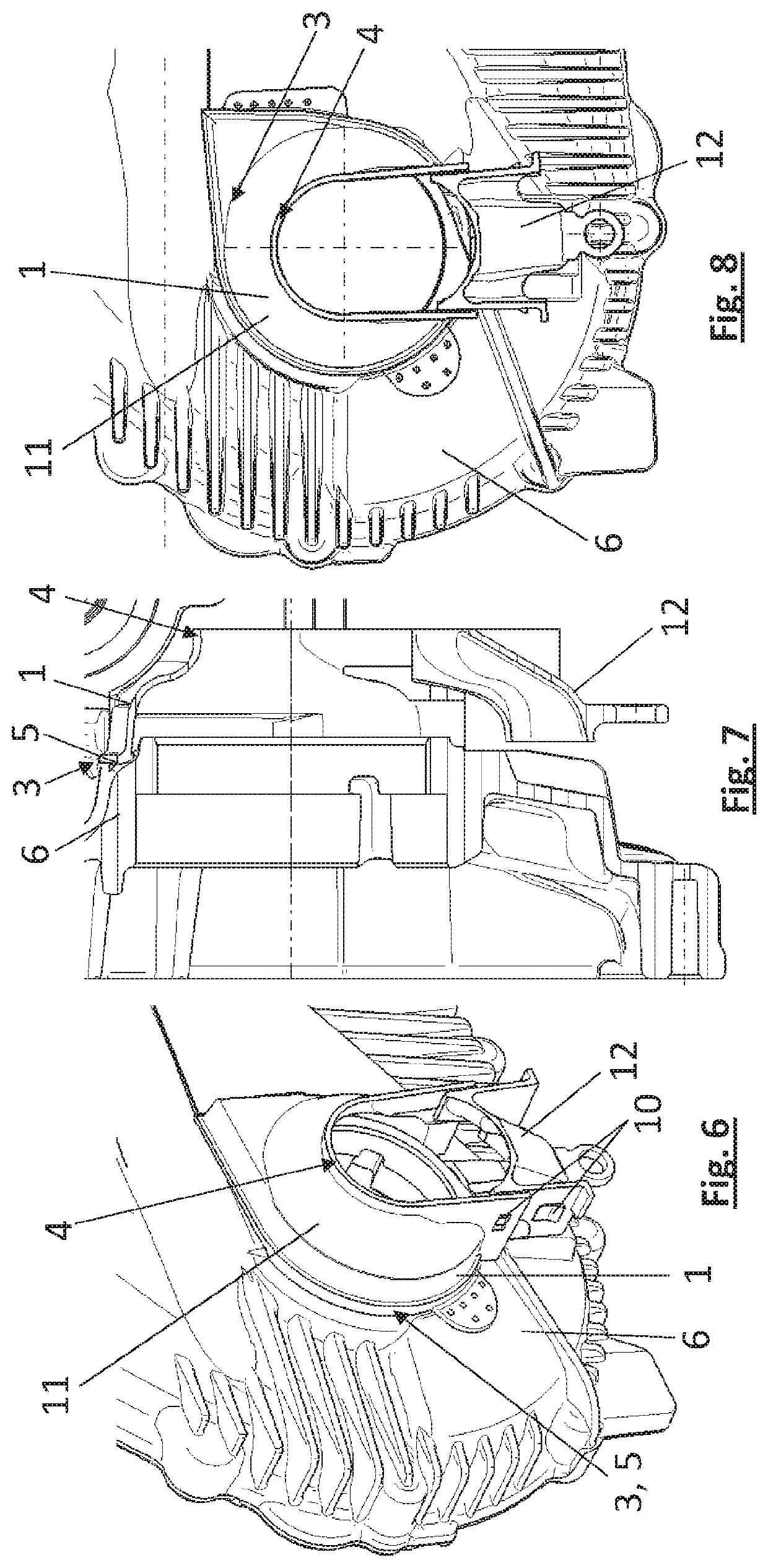
[0034]FIG. 1 shows a transfer gearbox according to the invention, comprising a housing 6 of the transfer gearbox and a shaft 2 at a shaft output of the transfer gearbox as well as a protective covering according to the invention.

[0035]The protective covering for the shaft output of the transfer gearbox comprises a solid, inelastic protective covering body 1, preferably made from plastic, which has substantially the form of a frustoconical casing in order to surround the shaft 2 in the region of the shaft output, having a larger first opening 3 at a first axial end and a smaller second opening 4 at a second axial end, situated opposite from the first end, of the protective covering body 1.

[0036]The second opening 4 surrounds the shaft 2 in a non-sealing manner, such that a gap 8 is formed at least in certain portions between the peripheral portion of the protective covering body 1 and the shaft 2, preferably a gap 8 is formed around the full periphery between the peripheral portion o...


PUM


Abstract

A protective covering for a shaft output of a transfer gearbox, comprising a solid, inelastic protective covering body, wherein the protective covering body has substantially the form of a frustoconical casing in order to surround a shaft in the region of the shaft output, having a first opening at a first axial end and a second opening at a second axial end, situated opposite from the first end, of the protective covering body, wherein the first opening is larger than the second opening, wherein the second opening is formed to surround the shaft, wherein, in the region of the first opening, a flange portion, lying at the top in the installed position, of the protective covering body is formed to be fastened to a housing of the transfer gearbox, wherein, in the region of the first opening, a portion, lying at the bottom in the installed position, of the protective covering body is formed to provide an outflow opening when the flange portion is fastened to the housing of the transfer gearbox.

Description

CROSS-REFERENCE TO RELATED APPLICATIONS[0001]This patent application claims priority to German Patent Application Serial No. 102019205870.1 filed Apr. 24, 2019, which is hereby incorporated by reference in its entirety.FIELD OF THE INVENTION[0002]The present invention relates to a protective covering for a shaft output of a transfer gearbox, and to a transfer gearbox comprising a shaft at a shaft output of the transfer gearbox and a protective covering for the shaft output.BACKGROUND OF THE INVENTION[0003]This section provides information related to the present disclosure which is not necessarily prior art[0004]Transfer gearboxes in motor vehicles serve to split an input torque over a plurality of outputs. The input torque and / or the output torques can be guided via rotatably mounted shafts respectively into or out of the transfer gearbox. Such shaft outputs of a transfer gearbox have the problem that, for example, water or dirt could penetrate into the transfer gearbox and may dama...

Claims


Application Information

Patent Timeline
Patent Type & Authority Patents(United States)
IPC IPC(8): F16D3/84F16H57/02F16H57/029
CPCF16D3/841F16H57/029F16H57/021
Inventor EIBLER, GERHARD
Owner MAGNA POWERTRAIN AG & CO KG
Why Eureka
Try Eureka