
Joint locking mechanism of passive robotic arm

a technology of joint locking and robotic arm, which is applied in the direction of mechanical equipment, surgical instruments, manufacturing tools, etc., can solve the problems of limited application of hydraulic and pneumatic joint locking mechanisms, affecting reducing the safety of patients, so as to achieve the effect of simplifying installation

Active Publication Date: 2022-06-21
SUZHOU UNIV
View PDF9 Cites 0 Cited by
  • Summary
  • Abstract
  • Description
  • Claims
  • Application Information

AI Technical Summary

Benefits of technology

[0008]Preferably, the joint output shaft is provided with a key mounting slot. A key is mounted within the key mounting slot. The key is protruded relative to the surface of the joint output shaft. A spline is further sleeved over the joint output shaft. The friction disk is fixed to the joint output shaft via the spline. The key is used to prevent the spline from sliding relative to the joint output shaft. The spline can simplify installation and prevent the friction disk from sliding relative to the joint output shaft.

Problems solved by technology

It has been shown that one of the major challenges for medical robots to be applied in clinics according to research and clinical practice about medical robots over the past 30 years is the safety.
And in particular, the robot powered electrically, hydraulically or pneumatically is an open loop device, which interacts directly with the surgeon and patient and thus brings a lot of psychological pressure on clinicians.
Because of bringing contamination to the operating room and the large size, hydraulic and pneumatic joint locking mechanisms' application is limited.
Although electromagnetic locking mechanisms following the same principle of the power-off braking have simple structures, they can only provide limited locking force with micro size.

Method used


Image

  • Joint locking mechanism of passive robotic arm
  • Joint locking mechanism of passive robotic arm

Examples


Embodiment Construction

[0016]The present application will be further described with reference to the drawings and specific embodiments to enable those skilled in the art to have better understanding and implement the present application, but the embodiments described herein are not intended to limit the protection scope of the present application.

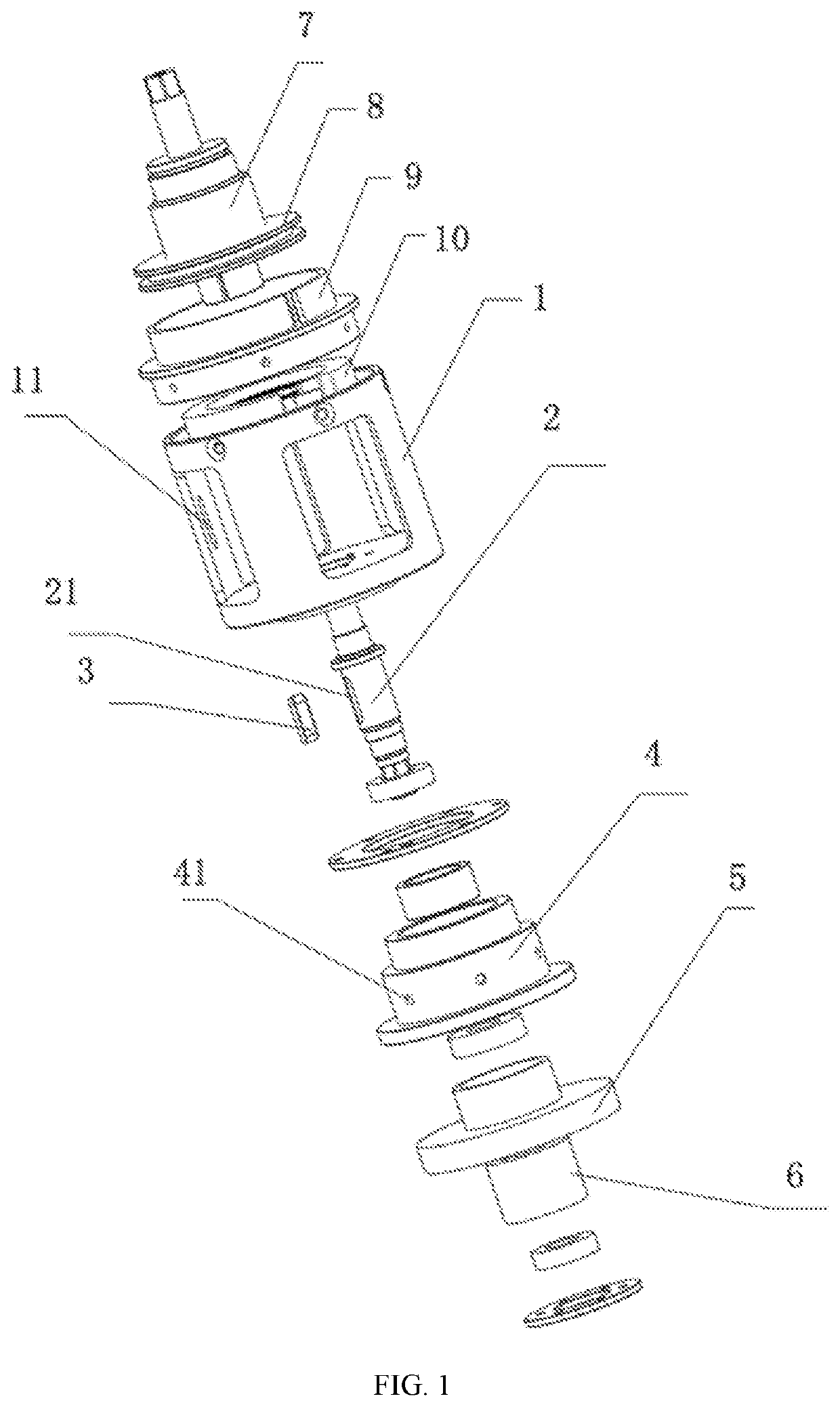
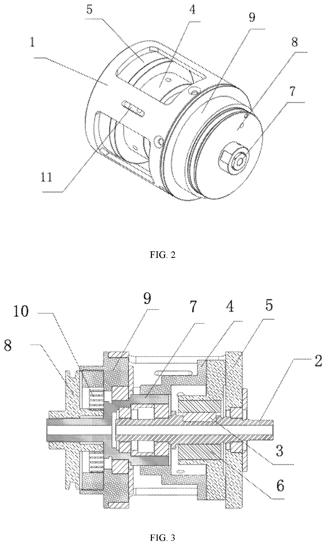
[0017]As shown in the drawings, the present application provides a joint locking mechanism of a passive robotic arm, comprising: an output assembly, including a joint output shaft 2, and a friction disk 5 fixed to the joint output shaft 2; a braking assembly, including a threaded shaft 7 arranged coaxially with the joint output shaft 2, a threaded sleeve 4 threaded to the threaded shaft 7, a rotary disk 8 connected fixedly to the threaded shaft 7, an end cap 9 rotatable relative to the rotary disk 8, and a scroll spring 10 generating a rotational force on the threaded shaft 7. The scroll spring 10 has one end connected fixedly to the end cap 9 and the other end c...


PUM


Abstract

A joint locking mechanism of a passive robotic arm includes: an output assembly, including a joint output shaft, and a friction disk fixed to the joint output shaft; a braking assembly, including a threaded shaft arranged coaxially with the joint output shaft, a threaded sleeve threaded to the threaded shaft, a rotary disk connected fixedly to the threaded shaft, an end cap rotatable relative to the rotary disk, and a scroll spring generating a rotational force on the threaded shaft. The scroll spring has one end connected fixedly to the end cap and the other end connected to the rotary disk or the threaded shaft. The threaded sleeve is abutted tightly against the friction disk.

Description

[0001]This application is the National Phase Application of PCT / CN2018 / 072932, filed on Jan. 17, 2018, which claims priority to Chinese Patent Application No.: 201711483123.5, filed on Dec. 29, 2017, each of which is incorporated by reference for all purposes as if fully set forth herein.FIELD OF THE INVENTION[0002]The present application relates to a joint locking mechanism of a passive robotic arm.BACKGROUND OF THE INVENTION[0003]Recently, with the development in medical robots, medical robots have become an important branch in the field of robots and also an important research subject in the field of biomedical engineering. It has been shown that one of the major challenges for medical robots to be applied in clinics according to research and clinical practice about medical robots over the past 30 years is the safety. And in particular, the robot powered electrically, hydraulically or pneumatically is an open loop device, which interacts directly with the surgeon and patient and ...

Claims


Application Information

Patent Timeline
Patent Type & Authority Patents(United States)
IPC IPC(8): F16D55/02F16D65/18A61B34/30B25J9/10F16D121/16
CPCA61B34/30B25J9/109F16D55/02F16D2121/16A61B34/70B25J17/00B25J19/0004F16D65/186F16D2125/40F16D59/02F16D2121/005F16D2121/14A61B90/50A61B2090/508
Inventor KUANG, SHAOLONGLI, JINZHONGZHANG, LILIN, ANDISHA, LIANSENYU, SHUMEIZHANG, FENGFENGSUN, LINING
Owner SUZHOU UNIV
Learn More