
Printing apparatus and printing method

a printing apparatus and printing method technology, applied in printing, other printing apparatus, etc., can solve the problems of density unevenness in the image printed on the print object, and achieve the effect of constant jetting speed of droplets and density unevenness

Active Publication Date: 2022-05-24
BROTHER KOGYO KK
View PDF6 Cites 0 Cited by
  • Summary
  • Abstract
  • Description
  • Claims
  • Application Information

AI Technical Summary

Benefits of technology

The present invention is about a printing apparatus and method that can change the frequency at which ink is jetted from the nozzles based on the speed of the print object, while reducing density unevenness in the image being printed. The controller detects the speed of the print object and adjusts the frequency at which ink is jetted from the nozzles accordingly to ensure a constant speed of droplets being jetted, which prevents density unevenness in the printed image.

Problems solved by technology

However, if the jetting frequency of the head is changed based on the speed of the print object, then the jetting speed of the liquid jetted from the head will change depending on the jetting frequency of the head, so as to cause a problem that density unevenness arises in the image printed on the print object.

Method used


Image

  • Printing apparatus and printing method
  • Printing apparatus and printing method
  • Printing apparatus and printing method

Examples


Embodiment Construction

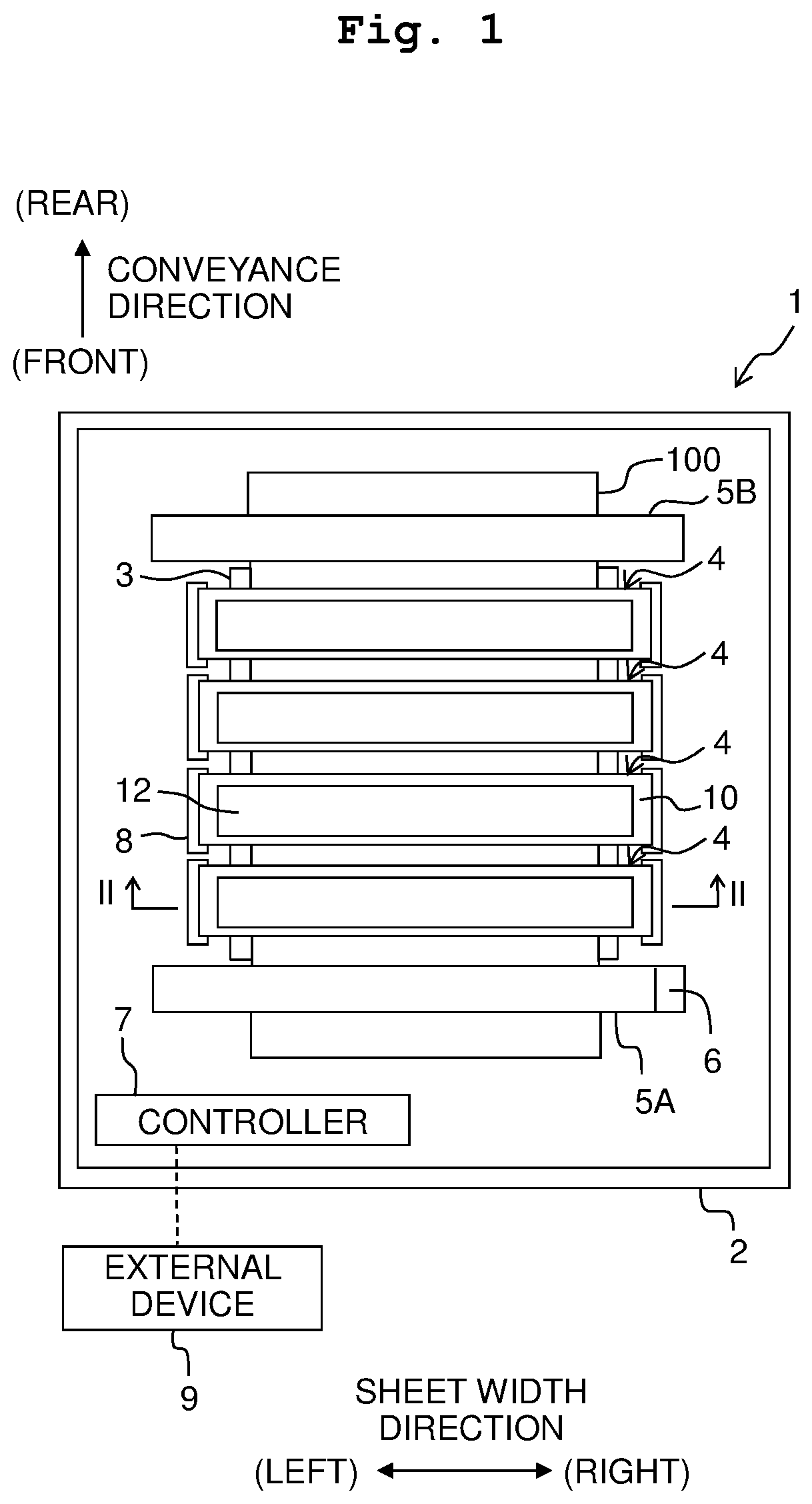
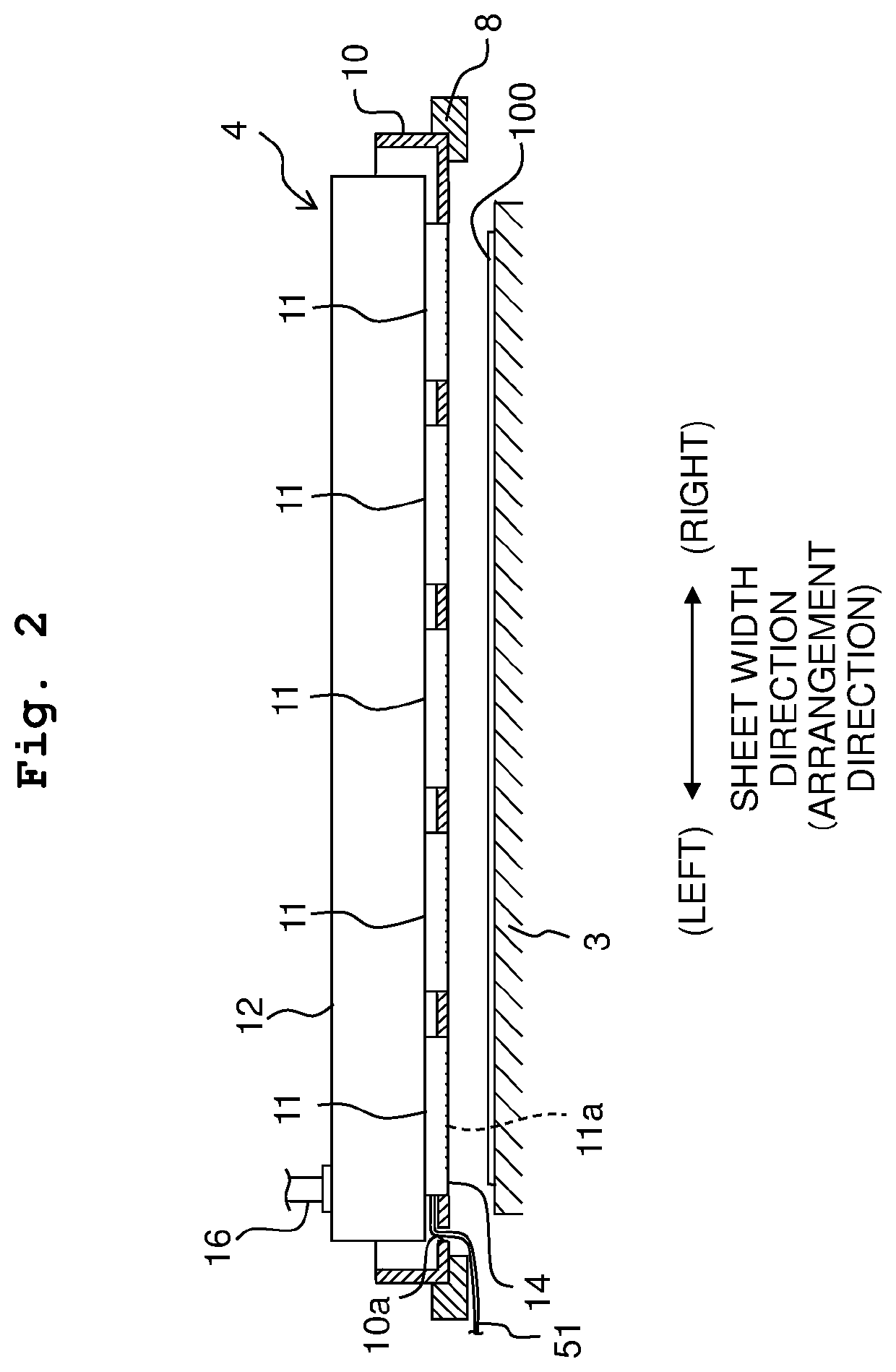
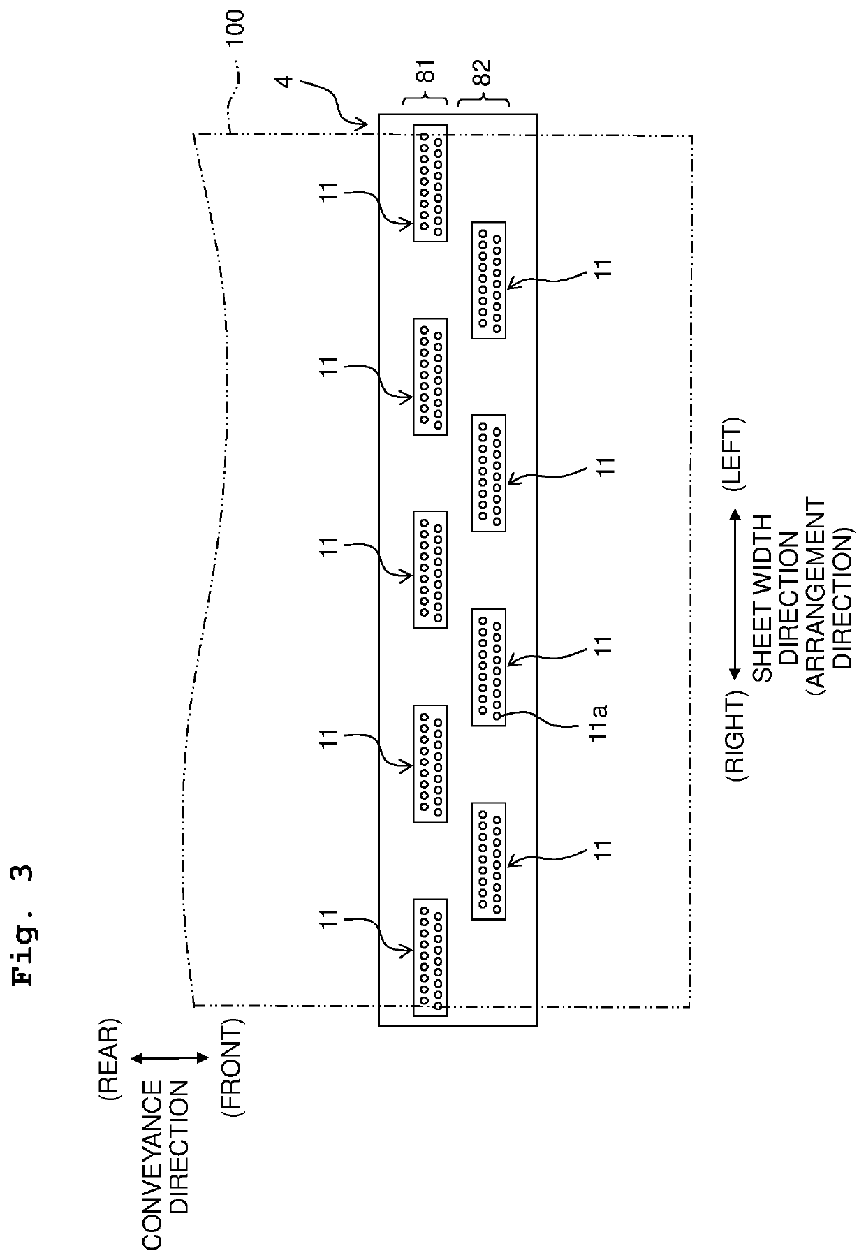
[0020]Hereinbelow, referring to FIGS. 1 to 9, an explanation will be made on a printing apparatus according to an embodiment of the present teaching.

[0021]In FIG. 1, the upstream side of a sheet 100 in a conveyance direction is defined as the front side of a printing apparatus 1, whereas the downstream side in the conveyance direction is defined as the rear side of the printing apparatus 1. Further, a left / right direction of the printing apparatus 1 is defined as a sheet width direction being orthogonal to the conveyance direction and parallel to the surface of the sheet 100 being conveyed (the surface parallel to the page surface of FIG. 1). Note that the left side of the figure is the left side of the printing apparatus 1 whereas the right side of the figure is the right side of the printing apparatus 1. Further, an up / down direction of the printing apparatus 1 is defined as the direction orthogonal to the conveyance surface of the sheet 100 (the direction orthogonal to the page s...


PUM


Abstract

A printing apparatus has a conveyance roller configured to convey a sheet in a first direction, an encoder provided at the conveyance roller, a head having a plurality of nozzles aligned in a second direction intersecting with the first direction and being configured to jet liquid to the sheet which is conveyed in the first direction by the conveyance roller and a controller having a power circuit configured to apply voltage to the head for jetting the liquid. The controller is configured to: determine a jetting frequency for the head based on a signal outputted from the encoder; and change an output voltage of the power circuit depending on the determined jetting frequency.

Description

CROSS REFERENCE TO RELATED APPLICATION[0001]The present application claims priority from Japanese Patent Application No. 2019-066482 filed on Mar. 29, 2019, the disclosure of which is incorporated herein by reference in its entirety.BACKGROUNDField of the Invention[0002]The present invention relates to a printing apparatus jetting ink from nozzles and a printing method utilizing the printing apparatus.Description of the Related Art[0003]There is known an ink jet printer including a motor driving a print object, a head jetting ink to the print object driven by the motor, and an encoder provided for the motor (see Japanese Patent Application Laid-open No. 10-151774). In such an ink jet printer, a signal is outputted from the encoder to indicate the speed of the print object, and the jetting frequency of the head is determined based on the speed of the print object.SUMMARY[0004]However, if the jetting frequency of the head is changed based on the speed of the print object, then the jet...

Claims


Application Information

Patent Timeline
Patent Type & Authority Patents(United States)
IPC IPC(8): B41J2/07B41J11/00B41J13/08
CPCB41J2/07B41J11/007B41J13/08B41J2/17546B41J2/1753B41J29/38B41J2/04581B41J2/04548B41J2/2146B41J2/2135
Inventor MAKINO, MASAHIRONAGANO, TAROKATO, DAIKIINOUE, HARULEE, JEONGBIN
Owner BROTHER KOGYO KK
Learn More