
Sizer for an extrusion machine with improved cooling and vacuum channels

a vacuum channel and extruder technology, applied in the direction of extruders with improved cooling and vacuum channels, can solve the problems of insufficient proximity and interaction with extruders to achieve both adequate cooling and adequate distribution of materials, and difficulty in achieving adequate cooling and distribution of materials, so as to improve cooling and vacuum channels. , the effect of less material and less material

Active Publication Date: 2022-05-17
ENGINEERED PROFILES LLC
View PDF11 Cites 0 Cited by
  • Summary
  • Abstract
  • Description
  • Claims
  • Application Information

AI Technical Summary

Benefits of technology

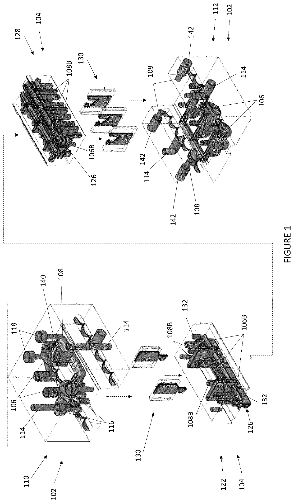
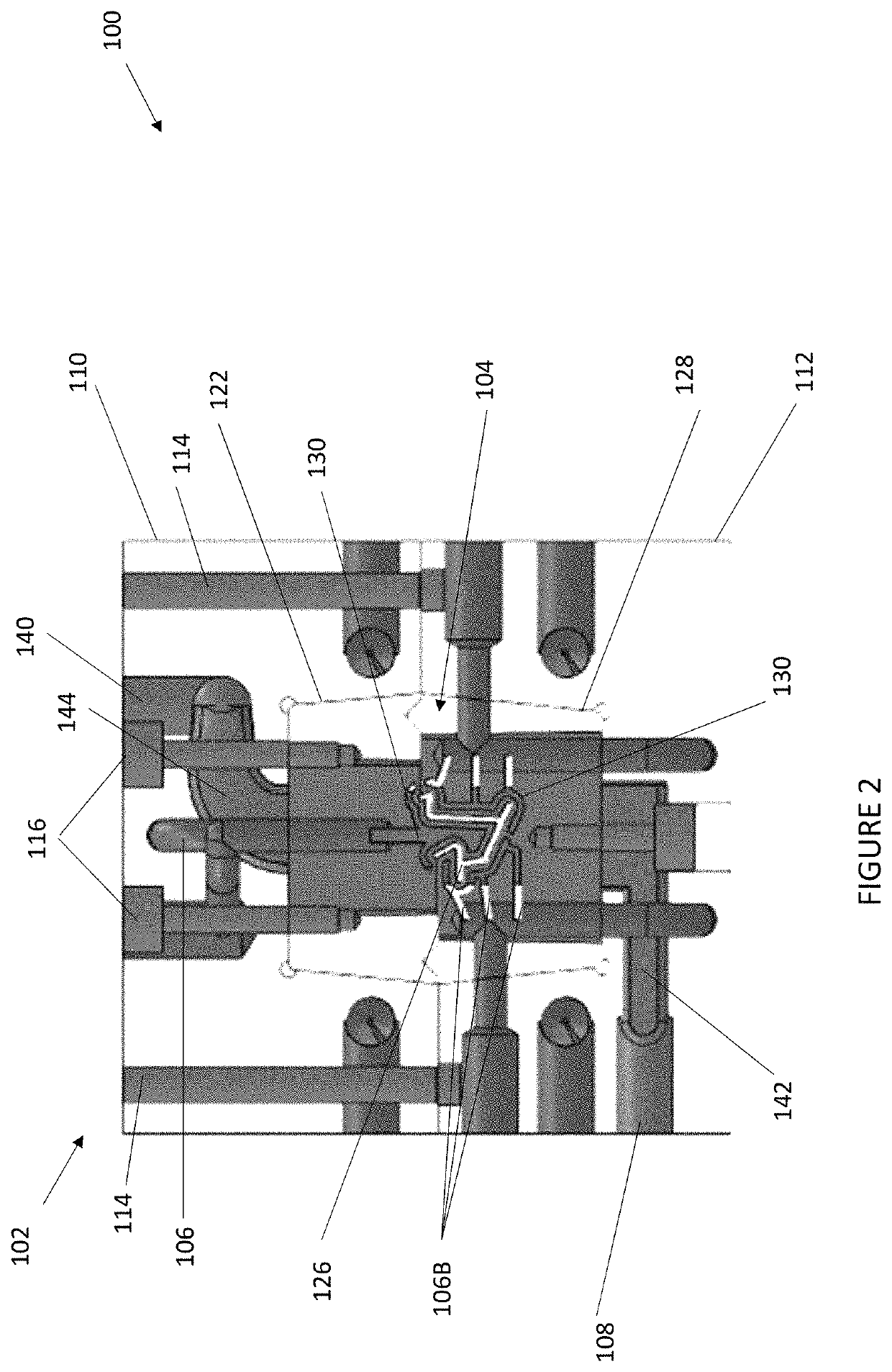
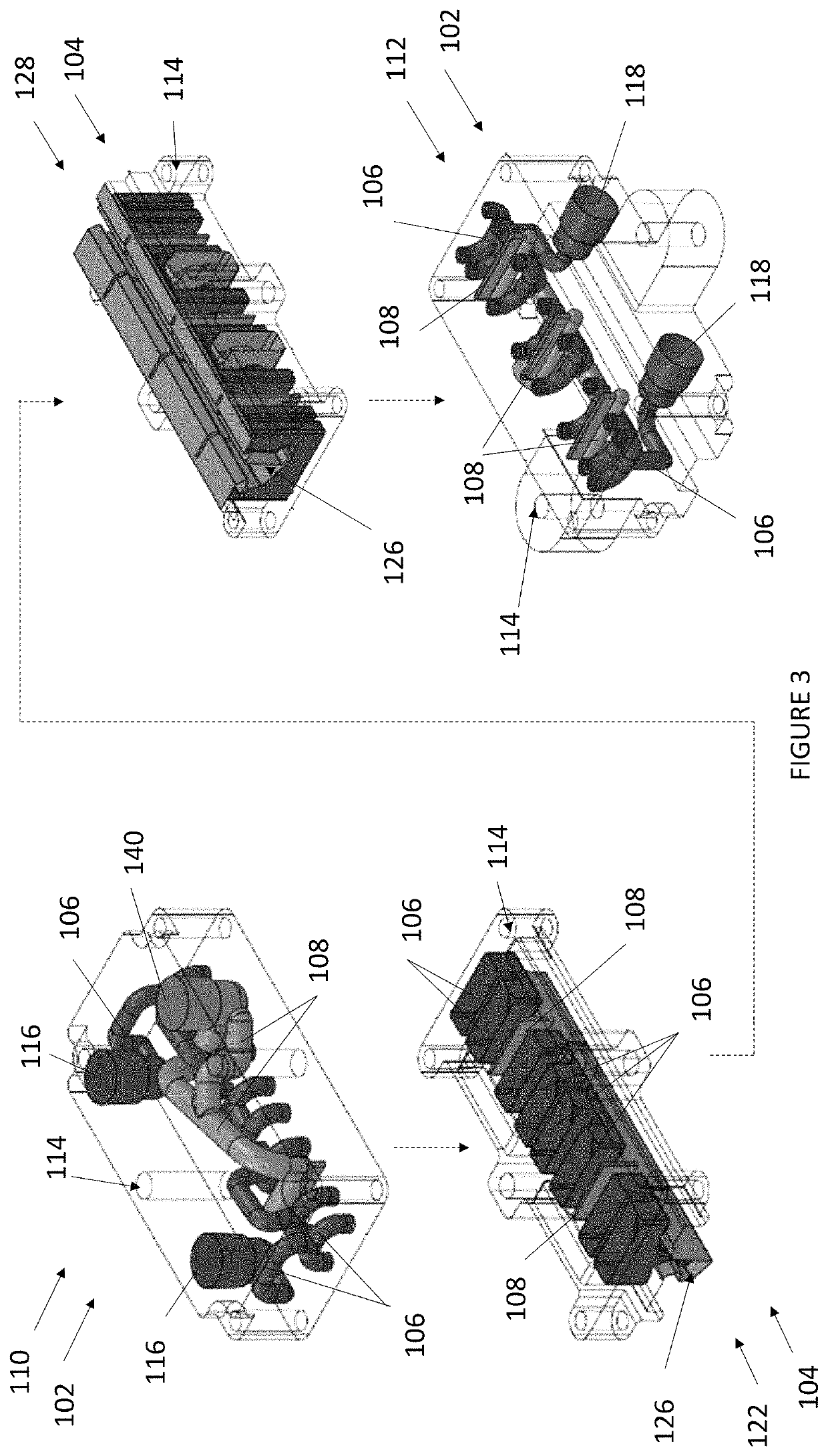
The patent describes a method to improve cooling and vacuum channels in a sizer by creating non-linear pathways that do not intersect. This increases the efficiency of the cooling flow and the transmission of vacuum forces. The method also allows for greater distribution of vacuum forces and faster manufacturing turnover. The non-linear cooling channels can induce turbulence in the cooling fluid and conform more closely to the extrusion channel. The method may also provide better cooling and vacuum channels in more sizer space by restricting them only by the volume of the sizer. The patent also mentions the use of vortexes or other shapes to cool the profile as needed.

Problems solved by technology

Without the vacuum channels, gravity might cause undesired deformations.
However, these vacuum channels create obstacles for cooling channels, which may be required to adequately cool the extrudate.
As both the vacuum and cooling channels require interaction with the extrusion channel, positioning both types of channels to in a way which provides sufficient proximity and interaction with the extrudate to achieve both adequate cooling and adequate distribution of material is spatially challenging.
For example, channels manufactured by such techniques cannot contain non-linear pathways (e.g., curves) to avoid other channels.
These intersections do not provide for efficient flow of cooling fluids or transmission of vacuum forces.
Further still, such drilling generally results in round channels, which are not always desirable.

Method used


Image

  • Sizer for an extrusion machine with improved cooling and vacuum channels
  • Sizer for an extrusion machine with improved cooling and vacuum channels
  • Sizer for an extrusion machine with improved cooling and vacuum channels

Examples


Embodiment Construction

)

[0025]Various embodiments of the present invention will now be described in detail with reference to the accompanying drawings. In the following description, specific details such as detailed configuration and components are merely provided to assist the overall understanding of these embodiments of the present invention. Therefore, it should be apparent to those skilled in the art that various changes and modifications of the embodiments described herein can be made without departing from the scope and spirit of the present invention. In addition, descriptions of well-known functions and constructions are omitted for clarity and conciseness.

[0026]Embodiments of the invention are described herein with reference to illustrations of idealized embodiments (and intermediate structures) of the invention. As such, variations from the shapes of the illustrations as a result, for example, of manufacturing techniques and / or tolerances, are to be expected. Thus, embodiments of the invention ...


PUM

PropertyMeasurementUnit
suction forcesaaaaaaaaaa
shapeaaaaaaaaaa
thermally conductiveaaaaaaaaaa

Abstract

A sizer for cooling an extrudate includes a core and a housing. The core includes an extrusion channel which accommodates the extrudate, a core cooling channel, and a core vacuum channel in fluid communication with said extrusion channel. The housing includes a housing cooling channel, a housing vacuum channel, a cooling intake, and a cooling exhaust. The housing cooling and vacuum channels having curved segments. The cooling intake and exhaust being in fluid communication with said housing cooling channel.

Description

CROSS-REFERENCE TO RELATED APPLICATIONS[0001]This application claims the benefit of U.S. Provisional Application No. 62 / 729,789 filed Sep. 11, 2018, the disclosures of which are hereby incorporated by reference as if fully restated herein.TECHNICAL FIELD[0002]Exemplary embodiments relate generally to sizers for creating extrusion profiles.BACKGROUND AND SUMMARY OF THE INVENTION[0003]Making a profile through extrusion requires two key components: a die to shape the molten material into the desired shape; and sizers to maintain the shape as the material cools to create a stable end product. Depending on the shape of the desired extrudate and the level of temperature reduction required, multiple sizers may be provided in succession to achieve adequate cooling. Typically, these sizers are made of two separately formed pieces that are joined together and define a hollow extrusion channel for the extrudate to flow through, although a single piece may be used as well.[0004]Within the sizer...

Claims


Application Information

Patent Timeline
Patent Type & Authority Patents(United States)
IPC IPC(8): B29C48/90B29C48/09B29C48/88B29C48/12
CPCB29C48/903B29C48/09B29C48/904B29C48/913B29C48/916B29C48/12B29C48/908B29C48/256B29C48/131B29C48/251
Inventor DHANAPAL, VICKRAMONEY, GARYMAY, ROGERKIMMES, TROY
Owner ENGINEERED PROFILES LLC
Learn More