
Three-in-one toy projectile launching assembly

a toy projectile and assembly technology, applied in toys, toys, white arms/cold weapons, etc., can solve the problems of limited toy projectile launcher and overall diversity, limited to one kind of game play, and limited toy projectile launcher and its overall diversity,

Active Publication Date: 2022-05-10
HILT GARRETT
View PDF36 Cites 2 Cited by
  • Summary
  • Abstract
  • Description
  • Claims
  • Application Information

AI Technical Summary

Benefits of technology

The present disclosure provides a toy projectile launching assembly capable of launching at least three different kinds of toy projectiles. The assembly includes a bow structure with a spring-biased plunger and a cavity for receiving different types of projectiles. The assembly also includes an elongate projectile shaft for launching elongated projectiles. The elongate projectile shaft has two recesses for receiving different types of projectiles, and a longitudinal air tunnel for ejecting the projectile. The assembly allows for easy launching of different types of toy projectiles with a single launching system.

Problems solved by technology

Toy projectile launching apparatus, such as toy guns, sling shots, bow and arrows, and darts guns are each individually capable of launching multiple projectiles, but are limited to adequately launching only one kind of projectile.
This limits the types of games that can be played with one toy projectile launcher and the overall diversity of the launcher.
Moreover, these toy projectile launchers include no means for altering their structure to enable interchanging of the types of projectiles launched therewith.
Presumably, one could attempt to launch different types of projectiles with any one of the launchers, however, each launcher is not particularly suited for every kind of projectile and as such would not function well and defeat the object of effectively launching a projectile and having fun.
While these units may be suitable for the particular purpose employed, or for general use, they would not be as suitable for the purpose of the present disclosure as disclosed hereafter.

Method used


Image

  • Three-in-one toy projectile launching assembly
  • Three-in-one toy projectile launching assembly
  • Three-in-one toy projectile launching assembly

Examples


Embodiment Construction

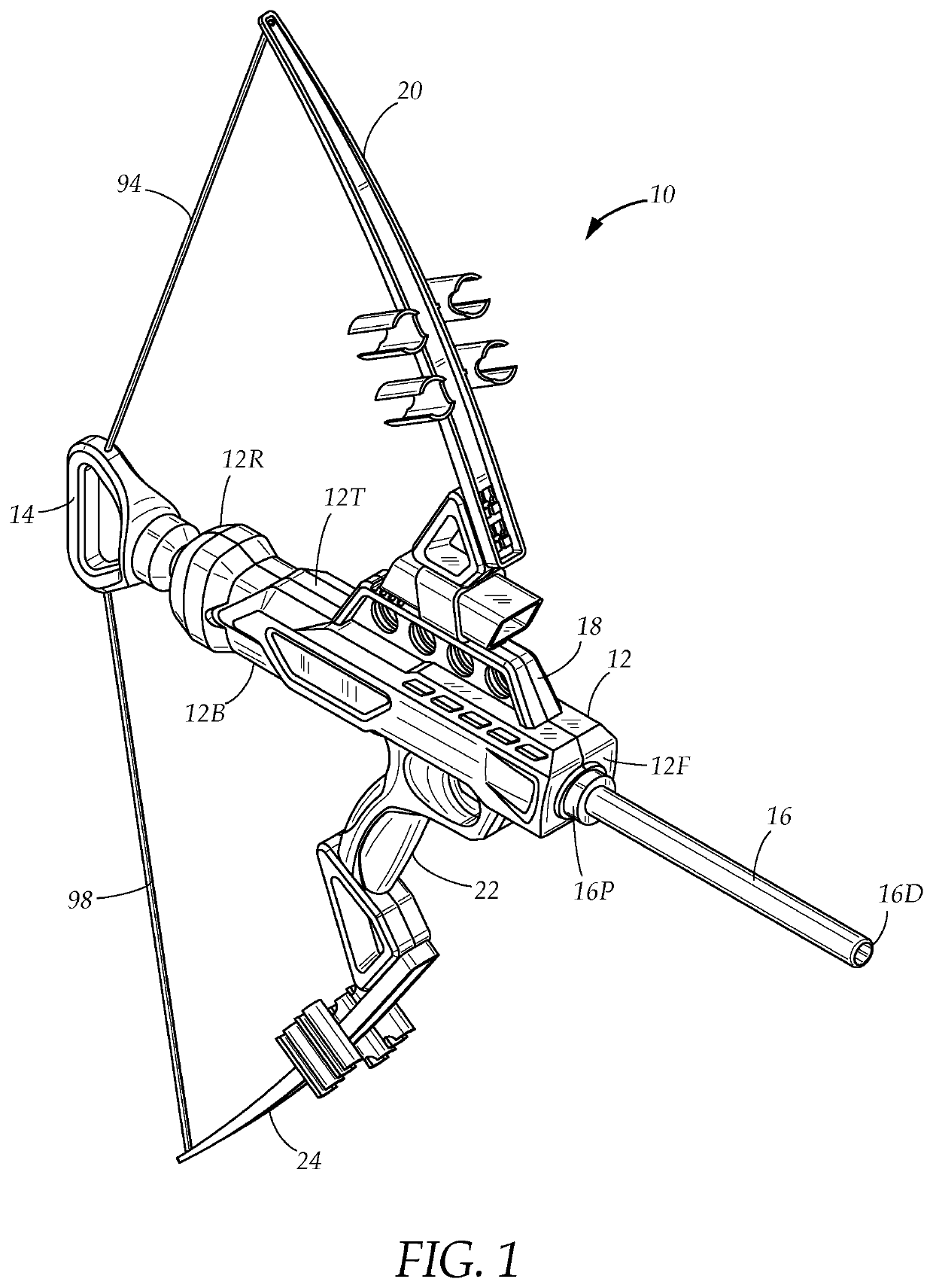
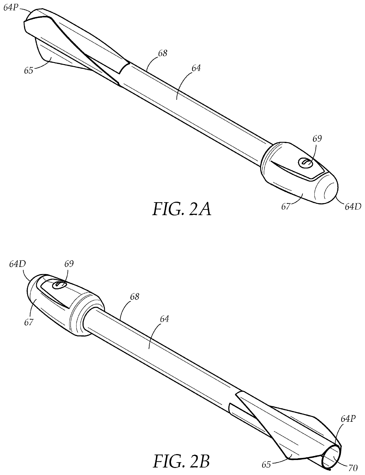
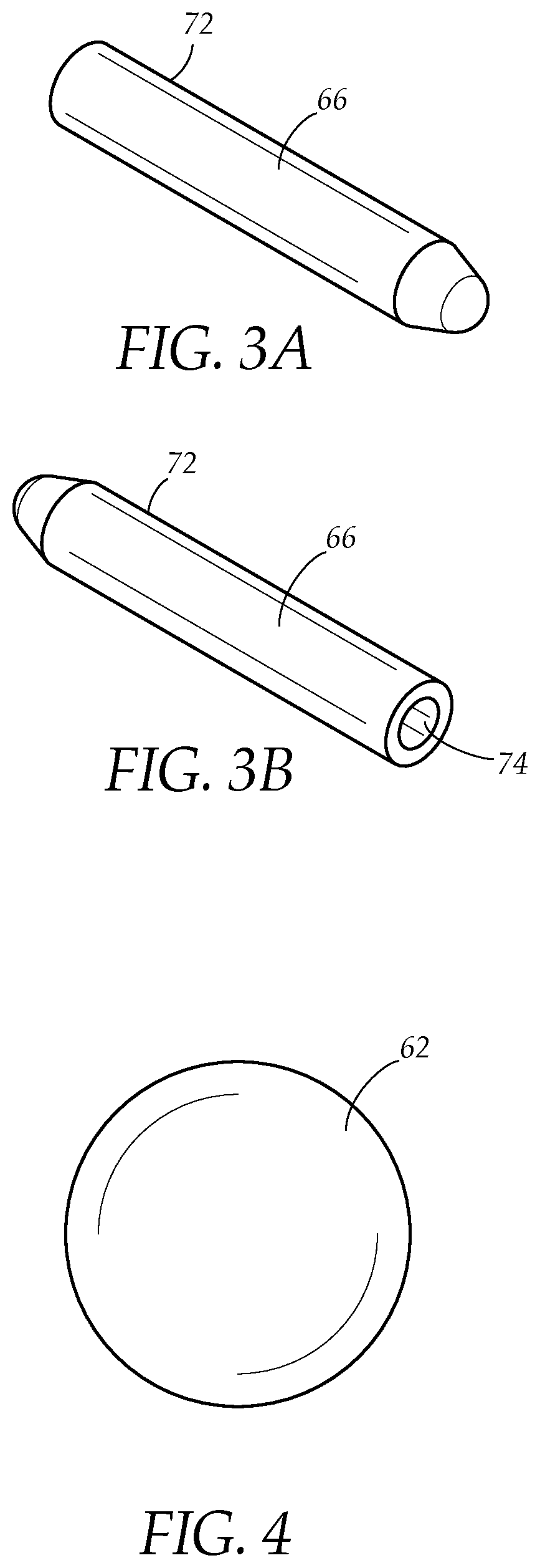
[0039]FIG. 1 illustrates a toy projectile launching assembly 10 capable of launching at least three different types of projectiles. In embodiments, the toy projectile launching assembly 10 comprises a bow structure including a body 12 having a top end 12T, a bottom end 12B opposite the top end 12T, a front end 12F, a rear end 12R opposite the front end 12F, a spring-biased plunger 14 extendable out of the body 12 for launching projectiles using compressed air driven through the body 12 when released from an extended position, and an elongate projectile shaft 16 having a proximal end 16P removably attachable to the front end 12F, and a distal end 16D opposite the proximal end 16P. In some embodiments, the assembly 10 comprises a projectile holder 18 extending upwardly from the body 12, a bow-shaped upper arm 20 extending upwardly from a projectile holder 18, a grip handle 22 extending downwardly from the body 12, and a bow-shaped lower arm 24 extending downwardly from the grip handle...


PUM


Abstract

An assembly for launching toy projectiles includes a body having a bore, a plunger extendable from the bore, and a shaft removably attachable to the body. The body includes a first recess having a first diameter for receiving a first projectile. The shaft includes a second diameter for receiving a second projectile therearound and a second recess having a third diameter for receiving a third projectile therein. The first diameter is substantially equal to a diameter of the first projectile, the second diameter is substantially equal to a diameter of the second projectile, and the third diameter is substantially equal to a diameter of the third projectile but smaller than the second diameter. The plunger drives air through the assembly when released from an extended position to eject any one of the first, second, or third projectiles positioned in the first recess, on the shaft, or in the second recess.

Description

TECHNICAL FIELD[0001]The present disclosure relates generally to toy projectile launching systems. More particularly, the present disclosure relates to a pneumatic toy bow assembly capable of launching at least three different types of toy projectiles.BACKGROUND[0002]Toy projectile launching apparatus, such as toy guns, sling shots, bow and arrows, and darts guns are each individually capable of launching multiple projectiles, but are limited to adequately launching only one kind of projectile. Indeed, their structures are designed and suited particularly for launching only one kind of projectile. This limits the types of games that can be played with one toy projectile launcher and the overall diversity of the launcher. For example, existing toy projectile launchers will include either an elastic string limiting the toy projectile launcher to an arrow-shaped or arrow-like projectile, a barrel sized and configured specifically to receive and eject either a ball projectile or a dart,...

Claims


Application Information

Patent Timeline
Patent Type & Authority Patents(United States)
IPC IPC(8): F41B5/00F41B11/642F41B11/89A63H27/00F41B7/08F42B6/10F42B6/02F42B6/00
CPCA63H27/005F41B7/08F41B11/642F41B11/89F42B6/003F42B6/02F42B6/10A63H33/18
Inventor HILT, GARRETT
Owner HILT GARRETT
Learn More