
Gate driving circuit and image display device including ihe same

a driving circuit and image display technology, applied in the direction of instruments, static indicating devices, etc., can solve the problems of limit in extending the charging period of image data voltage or the light emission period of each of the pixels, and achieve the effect of improving the quality of the image displayed on the image display device and increasing the charging rate of image data voltag

Active Publication Date: 2022-04-26
LG DISPLAY CO LTD
View PDF11 Cites 0 Cited by
  • Summary
  • Abstract
  • Description
  • Claims
  • Application Information

AI Technical Summary

Benefits of technology

[0008]Pixels may be driven to increase a charging rate of image data voltage charged in each of the pixels or to increase a light emission period or a color display period such that quality of the image displayed on an image display device is improved.
[0011]The present disclosure further provides the gate driving circuit to increase a data charging rate of green pixels having a greatest grayscale voltage difference or selectively increase a data charging rate of blue pixels having a greatest value of image data voltage, among red pixels, green pixels, and blue pixels, to improve image display quality, and an image display device including the gate driving circuit.
[0019]In addition, the gate driving circuit and the image display device including the gate driving circuit may selectively increase the data charging rate of the green pixels having a greatest grayscale voltage difference and increase the data charging rate of the blue pixels having a greatest value of image data voltage, among the red pixels, the green pixels, and the blue pixels, to improve image display quality.

Problems solved by technology

As every frame period may be limited according to sizes or driving characteristics of an image display panel, there is a limitation in extending an image data voltage charging period or a light emission period of each of the pixels.

Method used


Image

  • Gate driving circuit and image display device including ihe same
  • Gate driving circuit and image display device including ihe same
  • Gate driving circuit and image display device including ihe same

Examples


Embodiment Construction

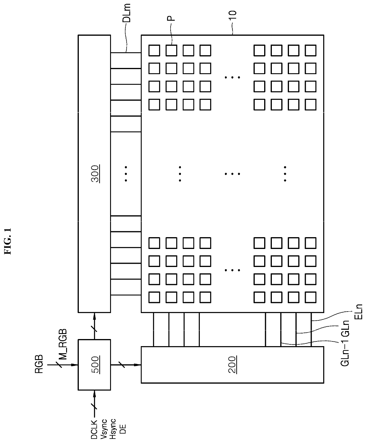
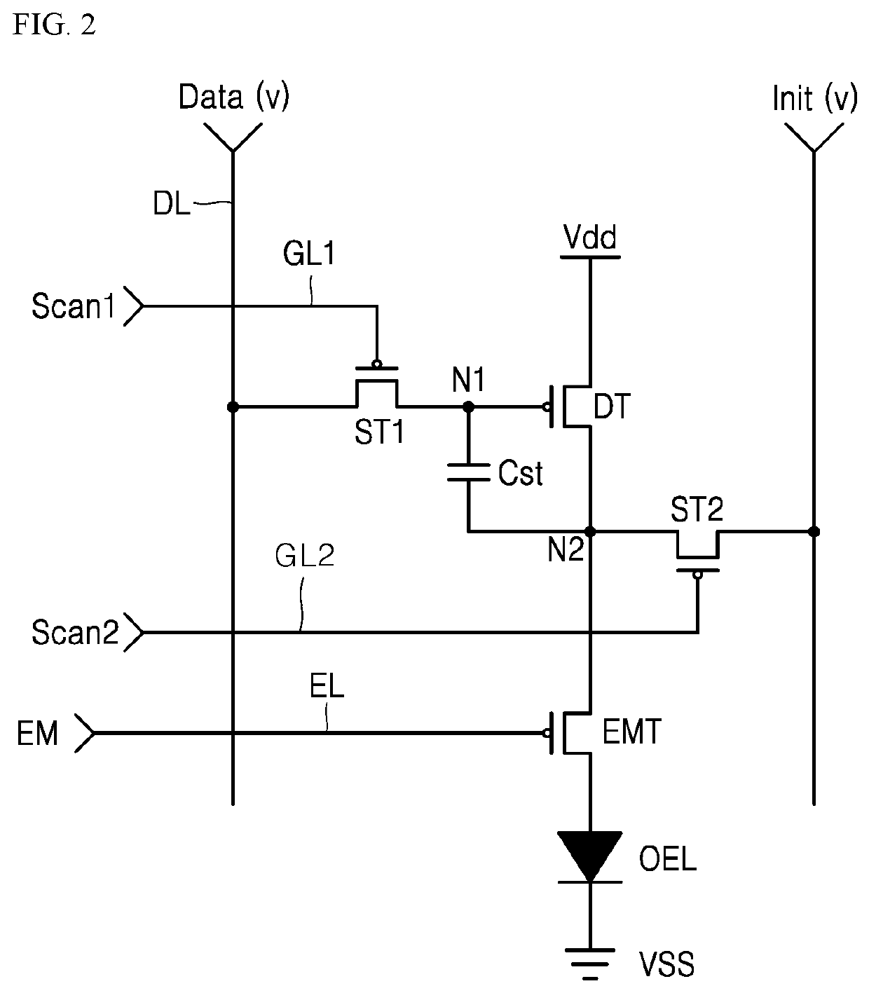
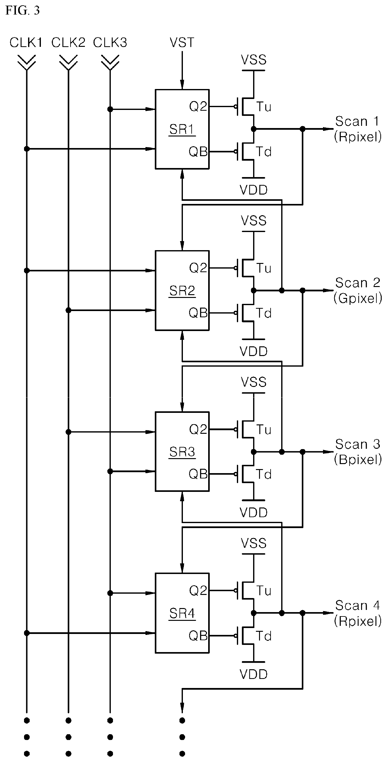
[0028]Some embodiments of the present disclosure and methods for achieving them will be apparent from the accompanying drawings and exemplary embodiments described below in detail. However, the present disclosure is not limited to the embodiments disclosed below, but is implemented in various different manners. Rather, these embodiments are provided so that this disclosure will be thorough and complete, and will fully convey the scope of the disclosure to those skilled in the art and the present disclosure is only defined by the scope of the claims.

[0029]Shapes, sizes, ratios, angles, numbers, and the like shown in the accompanying drawings for describing embodiments of the present disclosure are merely examples, and the present disclosure is not limited thereto. Like reference numerals denote like elements throughout the present disclosure. Further, in the following description, a detailed explanation of a well-known technology relating to the present disclosure may be omitted if i...


PUM


Abstract

A gate driving circuit and an image display device including the gate driving circuit are provided. In some embodiments of the present disclosure, the gate driving circuit includes a plurality of stages configured to sequentially and repeatedly output a plurality of scan pulses having different pulse widths in response to a gate control signal applied from a timing controller and the plurality of stages sequentially generate the plurality of scan pulses having different pulse widths and phase-delayed in response to three-phase clock pulses among the gate control signals and sequentially supply the plurality of scan pulses to gate lines of a display panel to selectively adjust a light emission period or a color display period for each red pixel, green pixel, and blue pixel, thereby improving image quality.

Description

CROSS-REFERENCE TO RELATED APPLICATION[0001]This application claims priority to and the benefit of Korean Patent Application No. 10-2019-0178069, filed Dec. 30, 2019, the disclosure of which is incorporated herein by reference in its entirety.BACKGROUNDTechnical Field[0002]The present disclosure relates to a gate driving circuit capable of selectively adjusting a light emission period or a color display period of each pixel to improve image quality, and one particular embodiment relates to an image display device including the gate driving circuit.Description of Related Art[0003]Image display devices may be used in various types of electronic products, such as mobile phones, tablet PCs, laptops, vehicles, and billboards. Examples of the image display devices may include liquid crystal display devices, organic light emitting diode (OLED) display devices, electro-wetting display devices, and field emission devices.[0004]Liquid crystal display devices or OLED display devices may includ...

Claims


Application Information

Patent Timeline
Patent Type & Authority Patents(United States)
IPC IPC(8): G09G3/3266G09G3/20G09G3/3225G09G3/3275G09G3/36
CPCG09G3/3266G09G3/2003G09G3/3225G09G3/3275G09G2310/0202G09G2310/0251G09G2310/08G09G3/3677G09G2310/0286G09G2310/06G09G2310/0264G09G2310/0243G09G2230/00
Inventor YU, JAESUNGKONG, CHUNGSIKLEE, SEWANYOO, JUHNSUKPARK, JUNGSOOSHIN, MIHEE
Owner LG DISPLAY CO LTD
Learn More