Integrated light source driver

a technology of light source driver and integrated light source, which is applied in the direction of semiconductor devices, light source support devices, lighting and heating devices, etc., can solve problems such as lamp defects, and achieve the effect of simplifying assembly

Active Publication Date: 2022-04-12
LEDVANCE GMBH
View PDF18 Cites 2 Cited by
  • Summary
  • Abstract
  • Description
  • Claims
  • Application Information

AI Technical Summary

Benefits of technology

[0006]Specifically, the invention is intended to provide a lamp base in which a connection can be formed between the light source carrier and the light source driver with no material bonding, thus permitting, for example, the simple and cost-effective replacement of a defective light source carrier.
[0009]The lamp base thus incorporates a housing, which is designed for the accommodation of a light source carrier for carrying a light source. The accommodation of the light source carrier proceeds by means of two mutually-opposing guide rails, which are preferably arranged within the housing. By means of these two mutually-opposing guide rails, the light source carrier can be accommodated in the housing in a form-fitted manner. To this end, each of the guide rails preferably incorporates at least one rail opening with an internal clearance. The light source carrier is, moreover, of a thickness which corresponds to this internal clearance, such that the light source carrier can be inserted into the lamp base in a simple and form-fitted manner.
[0010]It is particularly advantageous that the light source carrier can be arranged in the lamp base exclusively by means of form-fitting, so defective light source carriers can be replaced in a simple manner during the service life of the lamp.
[0015]Thus, in the simplest case, the guide rails incorporate a slot over their full length. Particularly advantageously, a particularly deep insertion of the light source carrier, thereby results in a lamp of a compact design.
[0016]In a preferred configuration, a limit stop to limit the depth of insertion of the carrier along the guide rails is provided, wherein it is specifically preferred that the limit stop is provided in the rail opening of the respective guide rails. Thus, upon the form-fitted insertion of the carrier into the guide rails, it is ensured that the light source carrier cannot be inserted beyond a predefined position. In this manner, moreover, assembly can be simplified, as the presence of the limit stop permits the carrier to be inserted with no further controls. The light source carrier, if it has been inserted to the depth of the limit stop, is thus automatically in the correct position. Additionally, the light source carrier is not easily pushed out again from the guide rails.
[0021]Particularly advantageously here, the symmetrical design permits cost-effective manufacture, for example by the production of two symmetrical half-shells using an injection-molding process.

Problems solved by technology

In general, this means that a defective light source carrier results in a defective lamp on economic grounds.

Method used


Image

  • Integrated light source driver
  • Integrated light source driver
  • Integrated light source driver

Examples


Embodiment Construction

[0041]Preferred exemplary embodiments are described hereinafter, with reference to the figures. Identical or similar components, or components with an equivalent function are identified in the various figures by the same reference symbols, and any repeated description of these elements has been omitted, to some extent, in the interests of avoiding redundancy.

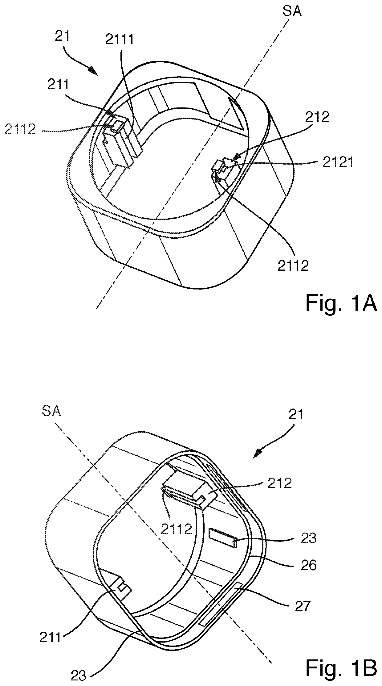
[0042]FIG. 1A shows a schematic representation of a perspective overhead view of the housing 21 of a lamp base 20 according to the invention.

[0043]The housing 21 is formed of an electrically non-conductive material, for example by means of an injection-molding method, and incorporates, in its interior, a first guide rail 211 and a second guide rail 212.

[0044]The guide rails 211, 212 are arranged in mutual opposition in the housing 21 and are designed to accommodate a light source carrier 22 in a form-fitted manner.

[0045]To this end, the two mutually-opposing guide rails 211, 212 each incorporate a rail opening 2111, 2121, wherei...


PUM

PropertyMeasurementUnit
lengthaaaaaaaaaa
depth of insertionaaaaaaaaaa
electrically non-conductiveaaaaaaaaaa

Abstract

A lamp base includes a housing for at least partial accommodation of a carrier for a light source. Two mutually-opposing guide rails are provided in the housing for the form-fitted insertion of the carrier. The technology is particularly applicable to carriers with LEDs as light sources and addresses problems with adhesive or soldered attachment of the light source carrier.

Description

CROSS-REFERENCE TO RELATED APPLICATIONS AND PRIORITY[0001]This patent application claims priority from German Patent Application No. 102017116949.0 filed Jul. 26, 2017, which is herein incorporated by reference in its entirety.TECHNICAL FIELD[0002]The present invention relates to a lamp base, specifically for an LED lamp, and to a lamp, specifically an LED lamp, incorporating such a lamp base.BACKGROUND[0003]Lamps or LED lamps are extensively known. They customarily comprise a light source carrier and a light source driver. The light source carrier comprises a light source proper, for example one or more LEDs, and the light source driver is designed to actuate or drive the light source proper. In general, both the light source carrier and the light source driver are at least partially arranged in a lamp base.[0004]Customarily, the light source carrier, which is generally of a plate-type design, is adhered or soldered onto the light source driver. In general, this means that a defect...

Claims


Application Information

Patent Timeline
Patent Type & Authority Patents(United States)
IPC IPC(8): F21V21/00F21K9/278F21K9/238F21V19/00F21Y107/90F21Y105/16F21Y103/10F21Y115/10F21Y107/50
CPCF21K9/278F21K9/238F21V19/0045F21Y2103/10F21Y2105/16F21Y2107/50F21Y2107/90F21Y2115/10F21K9/20F21V19/001F21V19/003F21V23/06
Inventor HOLLAENDER, PETERZIMMERMANN, MAXBIEBEL, ULRICH
Owner LEDVANCE GMBH
Why Eureka
Try Eureka