Panel mount for mounting signalling and control devices on control panels

a technology for controlling devices and mounting brackets, applied in electrical equipment, substation/switching arrangement details, etc., can solve the problems of not providing a seal, not tightly holding the panel, and wobble in place, so as to reduce the cost of installing panel mounted devices, the effect of fast, easy and complete installation

Active Publication Date: 2022-04-05
FLOYD BELL
View PDF22 Cites 0 Cited by
  • Summary
  • Abstract
  • Description
  • Claims
  • Application Information

AI Technical Summary

Benefits of technology

[0009]Preferably, the tubular housing body also includes a tubular male pre-assembly segment on the exterior surface of the tubular housing body. The tubular male pre-assembly segment permits the housing body to be pre-inserted partially into the grommet and into the bulging segment of the grommet without expanding any part of the grommet radially outward.
[0010]Preferably, the housing body and the grommet have cooperating structures to provide a withdrawal lock. An axially inward facing shoulder is formed into the interior wall of the grommet and an axially outward facing shoulder projects radially outward from the exterior surface of the housing. Upon completion of installation, these surfaces come into contact and prevent the housing from sliding axially out of the grommet.

Problems solved by technology

Although that traditional panel mount is effective, it requires simultaneous access to both the front and the back of the panel and requires several manipulative steps in order to mount it to a panel.
However, many panel mounts of that type do not provide a seal.
They often do not tightly hold the panel mount housing rigidly against the panel but instead allow it to wobble in place, especially if the panel mount has been subjected to vibration.
Some manufacturers use a spring to prevent wobble but at extreme cold temperatures the spring contracts or distorts and the installed structure wobbles.

Method used


Image

  • Panel mount for mounting signalling and control devices on control panels
  • Panel mount for mounting signalling and control devices on control panels
  • Panel mount for mounting signalling and control devices on control panels

Examples


Embodiment Construction

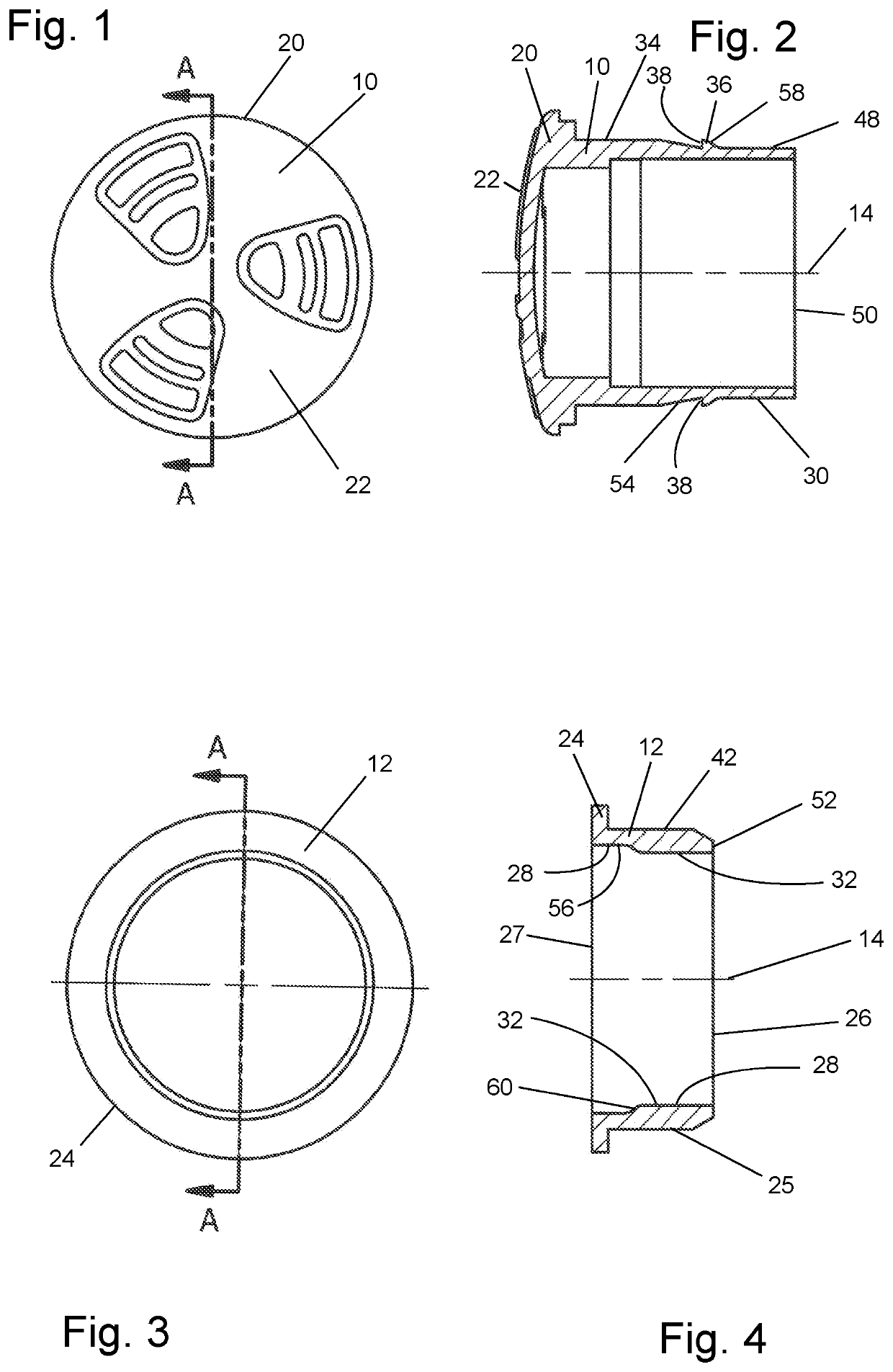
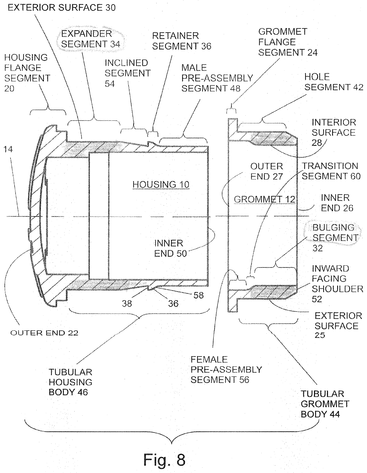
[0024]The following description of the invention begins with a description of a terminology convention and definitions that were adopted to describe the preferred embodiments of the invention and their operation during installation. The description of terminology and definitions is followed by an overview description of the preferred embodiments of the invention and their installation. The overview description will identify the principal component parts and fundamentals of their functional cooperation in general terms. Its purpose is to provide a general orientation to the components of the invention and their structural features and to additionally describe the sequence of steps to install an embodiment of the invention in a hole of a control panel. The overview description is followed by a description of more specific and detailed structural characteristics of the component parts of the preferred embodiments of the invention and their functional cooperation during the process of m...


PUM


Abstract

A panel mount for supporting an electronic device at a hole in a control panel and mountable with access to only the front of the panel. It has a housing that slides into a tubular elastomeric grommet. During installation, an expander segment of the housing slides within a bulging segment of the grommet to expand the grommet inward of the hole and for retaining the components within the hole. A tubular male pre-assembly segment on the exterior surface of the tubular housing permits the housing to be pre-inserted partially into the grommet without expanding any part of the grommet radially outward in preparation for inserting the assembled housing and grommet into the panel hole. A withdrawal lock prevents the housing from sliding axially out of the grommet after installation. The withdrawal lock includes a shoulder formed on the grommet and a shoulder formed on the housing.

Description

BACKGROUND OF THE INVENTION[0001]This invention is an improved panel mount for mounting electrical or other devices on panels such as control panels. Various kinds of electronic equipment commonly have control panels on which are mounted various panel mount devices such as audible or visual signaling devices, switches or meters. Many other kinds of machines and equipment, such as vehicles, machine tools, home appliances and farm equipment, also have control panels. Often, instead of a centralized control panel with an instrument cluster, there are multiple, separate, remotely-located panels some even having only a single device mounted on them. A control panel is often mounted to, or is a wall of, a cabinet or other enclosure which contains electronic or mechanical components in order to protect them from the environment or physical contact or to conceal them. Devices that require interaction with human operators but are also connected to the contained electronic or mechanical compo...

Claims


Application Information

Patent Timeline
Patent Type & Authority Patents(United States)
IPC IPC(8): H02G3/08H02G3/38H02G3/06
CPCH02G3/083H02G3/0691H02G3/286H02G3/22H02B1/048
Inventor ZIMMERMAN, GARY P.
Owner FLOYD BELL
Why Eureka
Try Eureka