
Suspension system and vehicle

a suspension system and suspension technology, applied in the field of suspension systems, can solve problems such as gap between parts, achieve the effects of facilitating the operation of the movable portion, and reducing the number of parts of the intermediate uni

Active Publication Date: 2022-03-15
YAMAHA MOTOR CO LTD
View PDF39 Cites 2 Cited by
  • Summary
  • Abstract
  • Description
  • Claims
  • Application Information

AI Technical Summary

Benefits of technology

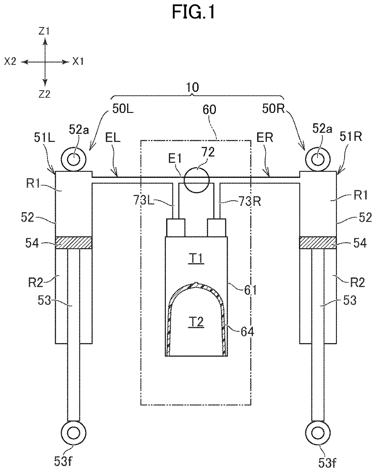
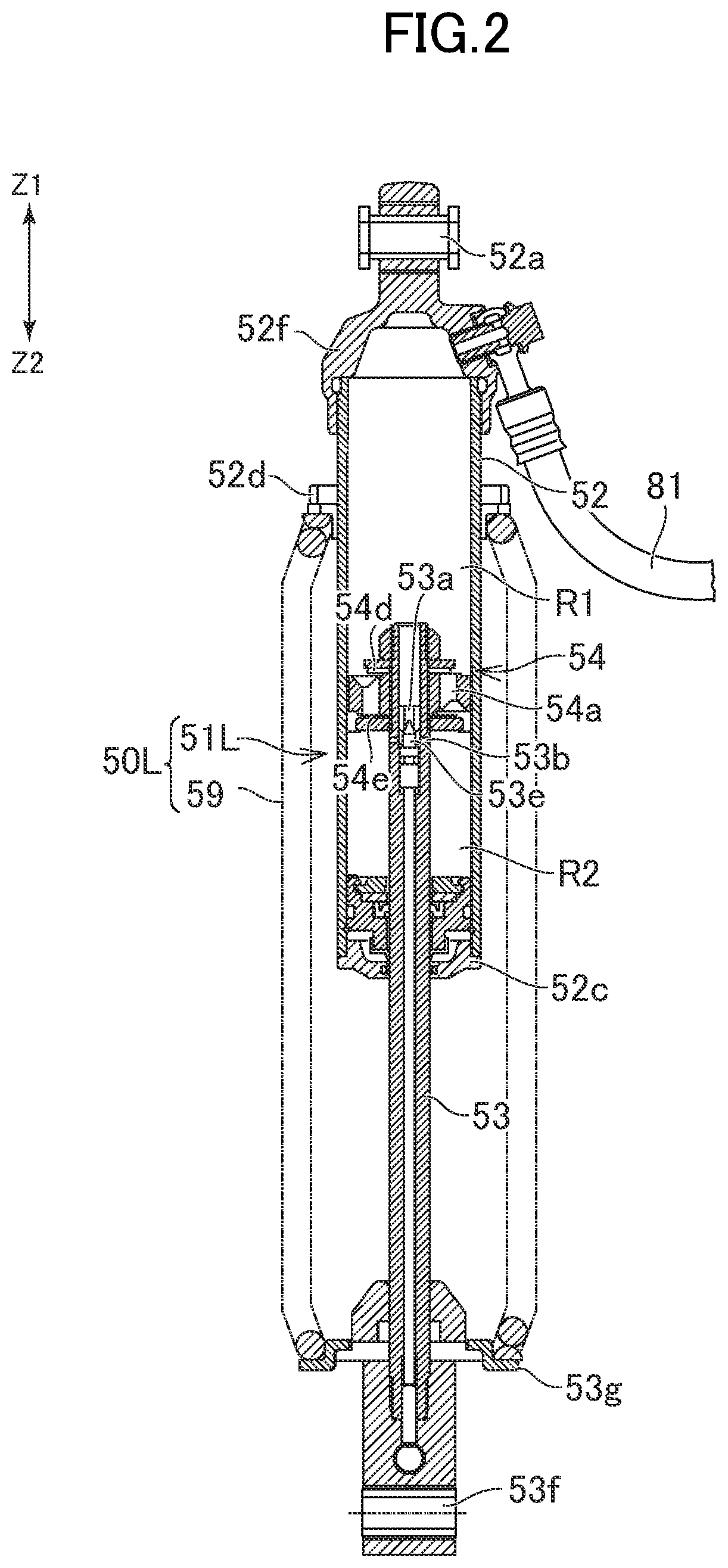
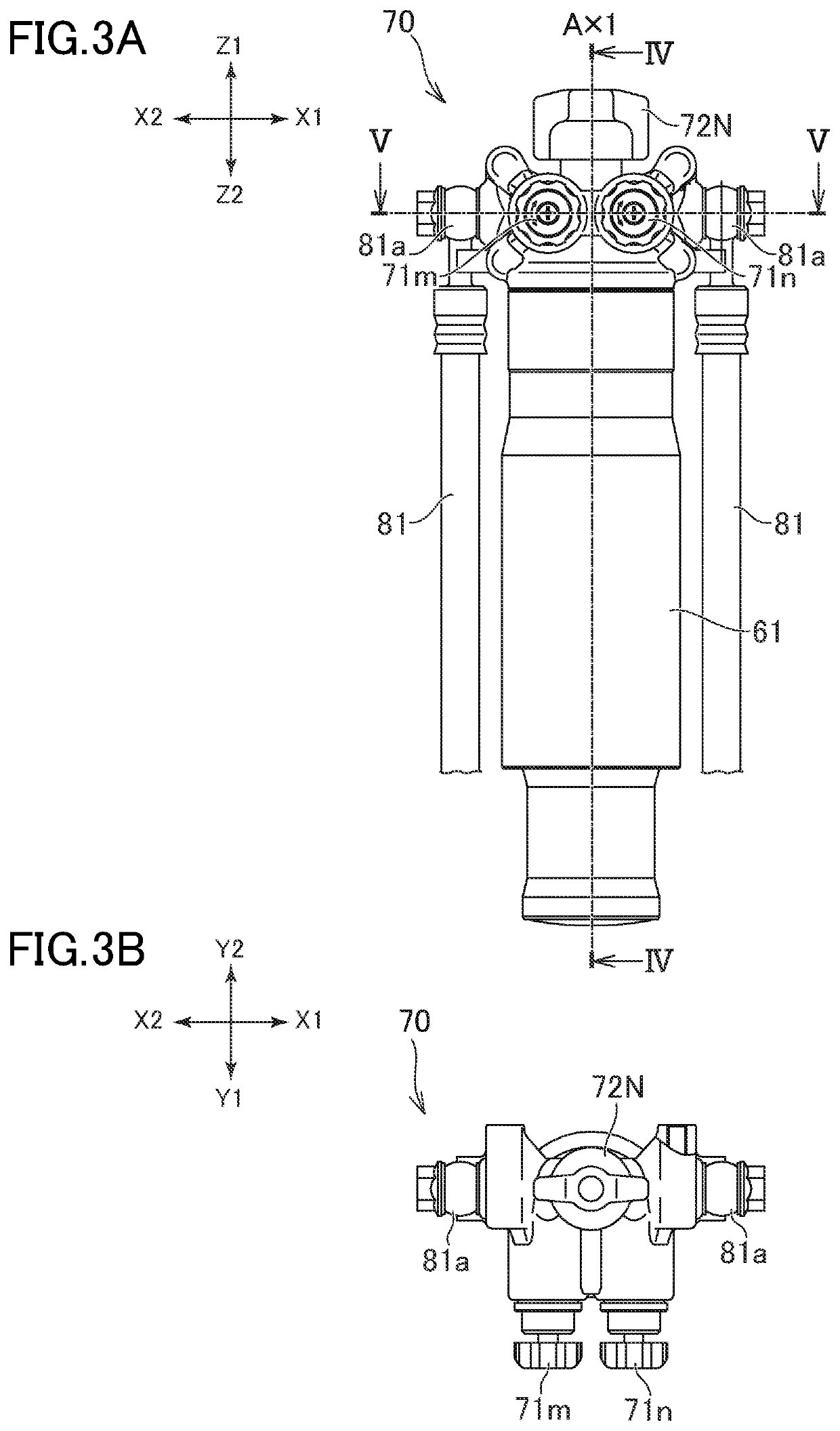
[0005](1) A suspension system proposed in the present disclosure includes a first damper having a cylinder in which an oil chamber is formed, a second damper having a cylinder in which an oil chamber is formed, and an intermediate unit which includes a case having an intermediate oil chamber connected to the oil chamber of the first damper and the oil chamber of the second damper and an intermediate gas chamber, and a partition member for partitioning the intermediate oil chamber and the intermediate gas chamber. The intermediate unit has a capacity adjustment mechanism including a movable portion which faces the intermediate gas chamber and of which a position or a size can be changed. The capacity adjustment mechanism allows a capacity of the intermediate gas chamber to be adjustable by changing the position or size of the movable portion. According to this suspension system, the responsiveness of the damper can be adjusted by adjusting the capacity of the intermediate gas chamber.
[0008](4) In the suspension system according to (3), the movable portion may be located on an outer side of the one end portion of the cylindrical main body. According to this, the capacity of the intermediate gas chamber can be increased.
[0009](5) In the suspension system according to (1) or (2), the movable portion may include a pressure receiving portion facing the intermediate gas chamber and an operated portion extending from the pressure receiving portion to an opposite side to the intermediate gas chamber and protruding outside the case. According to this, the operation of the movable portion may be facilitated.
[0010](6) In the suspension system according to (2), the intermediate unit may include a first damping force generating mechanism located on a first oil flow path which is a flow path between the intermediate oil chamber and the oil chamber of the first damper and a second damping force generating mechanism located on a second oil flow path which is a flow path between the intermediate oil chamber and the oil chamber of the second damper. The movable portion may be located on a side opposite to the first damping force generating mechanism and the second damping force generating mechanism in the direction along the axis of the cylindrical main body. According to this, it is possible to avoid a complicated layout of components in the intermediate unit.
[0012](8) The suspension system according to any one of (1) to (7), further may comprise an actuator for moving the position of the movable portion. According to this, the capacity of the intermediate gas chamber can be easily adjusted.
[0014](10) In the suspension system according to any one of (1) to (8), the position or size of the movable portion may be changed stepwise. According to this, the adjustment work by an operator on the capacity of the intermediate gas chamber can be simplified.

Problems solved by technology

However, if the responsiveness of the damper is slow, a gap is caused between the time at which the movement of the damper switches and the time at which a direction of the force generated by the damper switches.

Method used


Image

  • Suspension system and vehicle
  • Suspension system and vehicle
  • Suspension system and vehicle

Examples


Embodiment Construction

[0037]The terminology used herein is for the purpose of describing particular embodiments only and is not intended to be limiting of the invention. As used herein, the term “and / or” includes any and all combinations of one or more of the associated listed items. As used herein, the singular forms “a,”“an,” and “the” are intended to include the plural forms as well as the singular forms, unless the context clearly indicates otherwise. It will be further understood that the terms “comprises”, “comprising”, “includes”, and / or “including”, when used in this specification, specify the presence of stated features, steps, operations, elements, and / or components, but do not preclude the presence or addition of one or more other features, steps, operations, elements, components, and / or groups thereof.

[0038]Unless otherwise defined, all terms (including technical and scientific terms) used herein have the same meaning as commonly understood by one having ordinary skill in the art to which thi...


PUM


Abstract

In a suspension system in which the oil chambers of two dampers are connected, the responsiveness of the dampers can be adjusted. A suspension system has a left damper, a right damper, and an intermediate unit. A case of the intermediate unit has an intermediate oil chamber connected to an oil chamber of the left damper and the oil chamber of the right damper and an intermediate gas chamber. The intermediate oil chamber and the intermediate gas chamber are partitioned by a diaphragm. The intermediate unit has a capacity adjustment mechanism including a movable portion of which the position can be changed. The capacity adjustment mechanism adjusts the capacity of the intermediate gas chamber by changing the position of the movable portion.

Description

CROSS-REFERENCE TO RELATED APPLICATION[0001]The present application claims priority from Japanese application JP2019-070175 filed on Apr. 1, 2019, the content of which is hereby incorporated by reference, in its entirety, into this application.FIELD OF THE INVENTION[0002]The present disclosure relates to a suspension system included in a vehicle such as a four-wheeled vehicle or a snowmobile.BACKGROUND OF THE INVENTIONDescription of the Related Art[0003]JP 2017-136918A and JP H8-132846A disclose a suspension system having an intermediate unit disposed between a right damper and a left damper. The intermediate unit has an oil chamber (referred to as “intermediate oil chamber”), and a gas chamber (referred to as “intermediate gas chamber”) partitioned by a free piston. The free piston can move in an axial direction in a case (cylinder) forming the intermediate unit according to expansion and contraction of the intermediate oil chamber. The intermediate oil chamber is connected to oil ...

Claims


Application Information

Patent Timeline
Patent Type & Authority Patents(United States)
IPC IPC(8): B60N2/02B60G17/015B60G17/04B60G13/08B60G21/073
CPCB60G17/0424B60G13/08B60G21/073B60G2202/154B60G2300/322F16F9/064B60G2202/312B60G2200/144B60G2204/82B60G2204/8304B60G2206/41B60G15/062B60G17/0155B60G17/0272B60G17/033B60G2202/32B60G2204/62B60G2500/206B60G2500/22
Inventor KUBOTA, TAKAHIKO
Owner YAMAHA MOTOR CO LTD
Learn More