
Fan device and fan holder

a fan device and fan holder technology, applied in the field of fans, can solve the problems of inconvenient carrying, inconvenient folding of conventional fan devices, and inability to fold conventional fan devices, and achieve the effect of improving the problem of concentric movemen

Active Publication Date: 2022-03-08
LIU CHIA YUAN
View PDF7 Cites 0 Cited by
  • Summary
  • Abstract
  • Description
  • Claims
  • Application Information

AI Technical Summary

Benefits of technology

The present patent provides a fan device and holder that can be folded and stored, making it more convenient to carry. The fan device includes a seat and frame that can be rotated to fold onto the bracket, reducing the space needed for storage.

Problems solved by technology

However, the fan seat and the support rod of the conventional fan device are fixed to each other, so that the conventional fan device cannot be stored in a folded manner.
As a result, when a user is not using the conventional fan device, the conventional fan device takes up space and is inconvenient for carrying.

Method used


Image

  • Fan device and fan holder
  • Fan device and fan holder
  • Fan device and fan holder

Examples


first embodiment

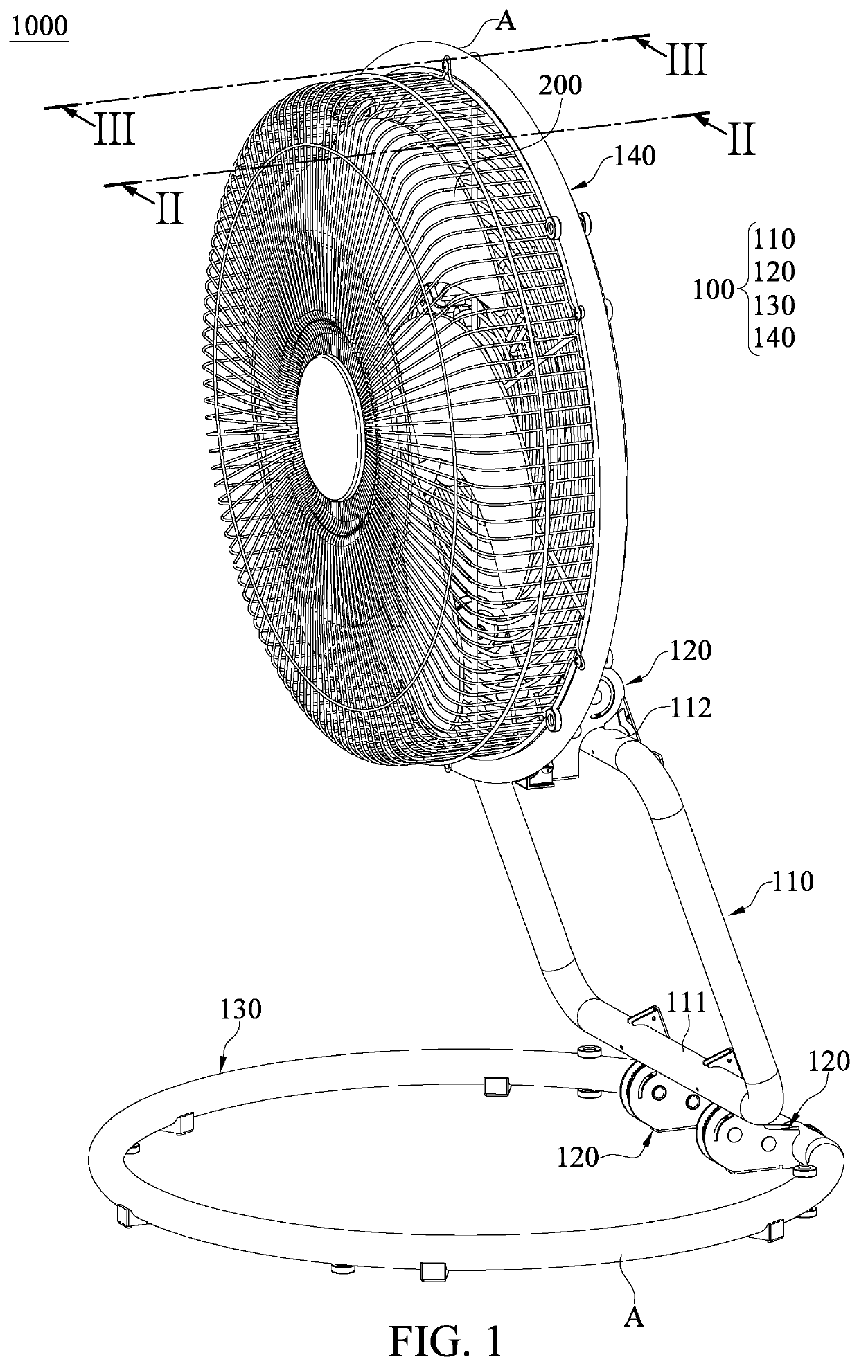
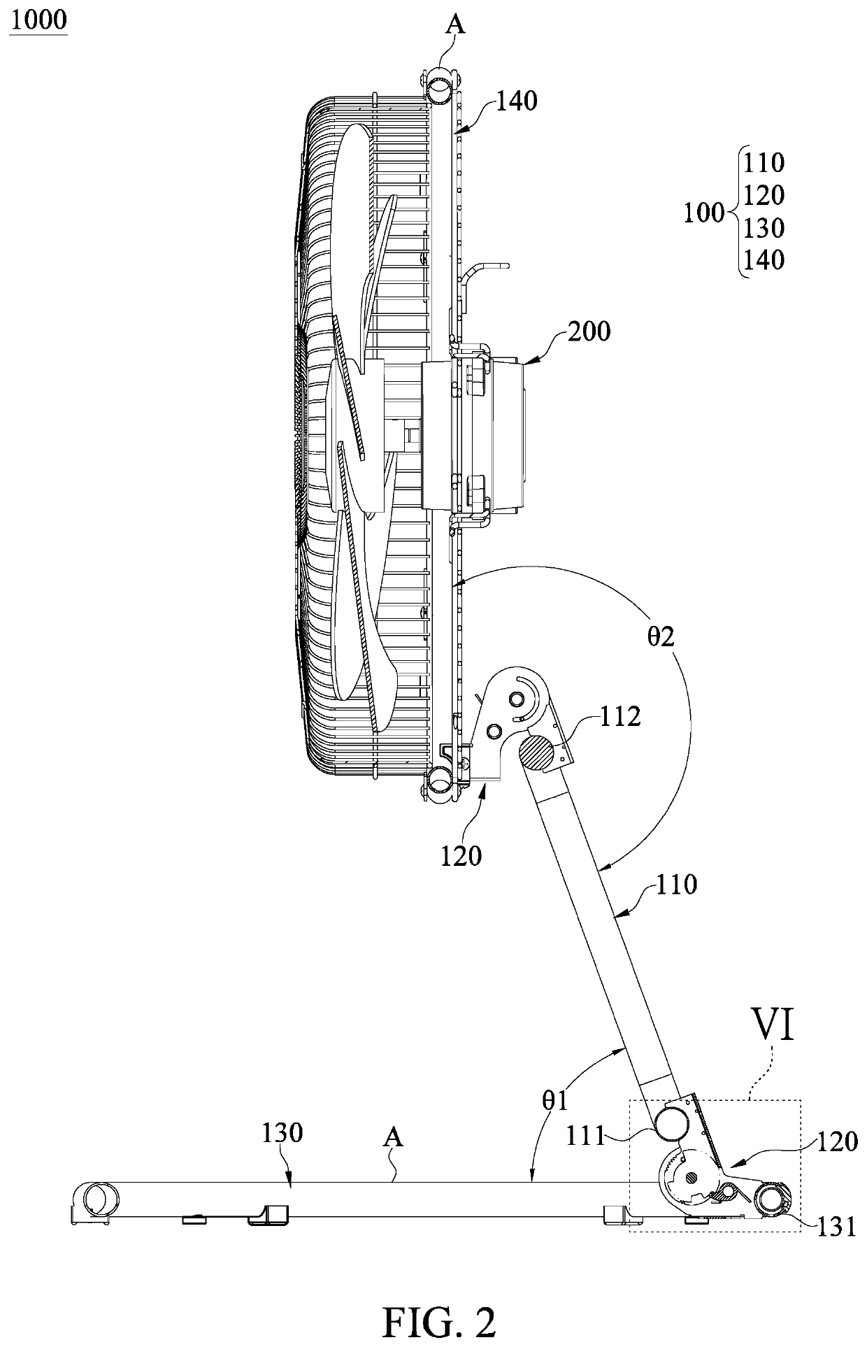
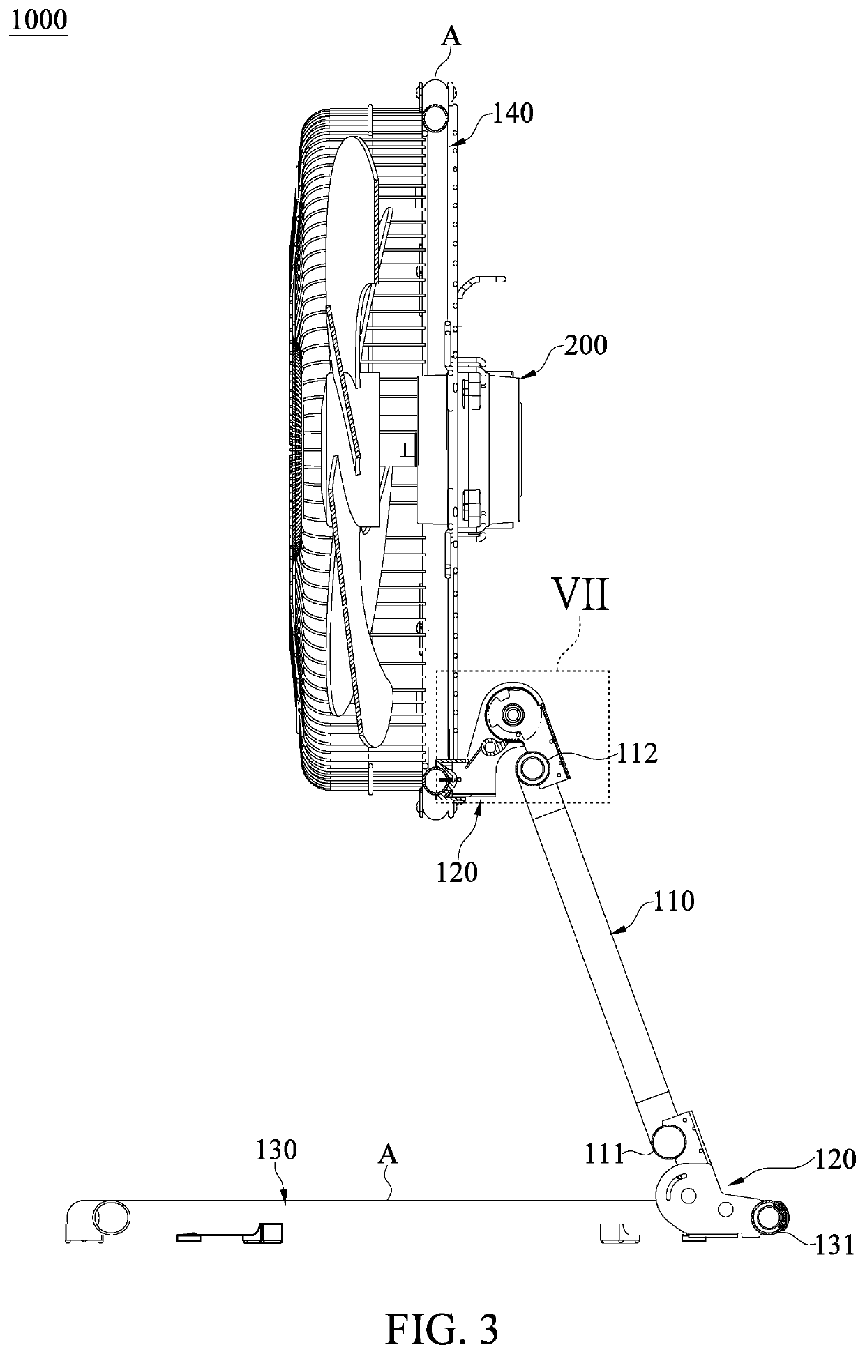
[0026]Referring to FIG. 1 to FIG. 13, a first embodiment of the present disclosure provides a fan device 1000 that can be stored in a folded manner to achieve the effect of reducing volume. In other words, any fan device that cannot be stored in a folded manner is not the fan device 1000 of the present disclosure, such as a fan device stored in a detached manner. The fan device 1000 includes a fan holder 100 and a fan 200 that is disposed on the fan holder 100.

[0027]It should be noted that the fan holder 100 and the fan 200 in the present embodiment are jointly defined as the fan device 1000, but the present disclosure is not limited thereto. For example, the fan holder 100 can be independently used (e.g., sold) or can be used in cooperation with other components. The following description describes the structure and connection relationship of each component of the fan device 1000.

[0028]The fan holder 100 includes a bracket 110, four ratchet sets 120 disposed on the bracket 110, a s...

second embodiment

[0044]Referring to FIG. 14 and FIG. 15, the greatest difference between the second embodiment and the first embodiment is that the fan holder 100 further includes a plurality of first connection members 150, a plurality of second connection members 160, and a plurality of support rods 170. The first connection members 150 are disposed on the frame 140, and each of the first connection members 150 includes a first connection groove 151 capable of being connected to any one of the support rods 170. The second connection members 160 are disposed on the seat 130, and each of the second connection members 160 includes a second connection groove 161 capable of being connected to any one of the support rods 170. Specifically, the number of the first connection members 150, the second connection members 160, and the support rods 170 in the present embodiment are the same. When the frame 140 and the bracket 110 are at the storage position B, the positions of the first connection members 150 ...


PUM


Abstract

A fan device and a fan holder are provided. The fan device includes the fan holder and a fan. The fan holder includes a bracket, four ratchet sets, a seat, and a frame. Each of two ends of the bracket is connected to two of the four ratchet sets. The seat is connected to the two of the four ratchet sets arranged to the one of two ends of the bracket. The frame is connected to the other two of the four ratchet sets arranged to the other one of two ends of the bracket. The seat and the frame are rotatable between a use position and a storage position relative to the bracket through the four ratchet sets. The fan is connected to the frame. The seat and the frame are rotated to the storage position, so that the bracket can be arranged on the seat.

Description

FIELD OF THE DISCLOSURE[0001]The present disclosure relates to a fan, and more particularly to a fan device and a fan holder for convenient storage.BACKGROUND OF THE DISCLOSURE[0002]A conventional fan device includes a fan seat and a fan that is disposed on the fan seat. The fan seat is composed of a bottom plate and a support rod that is disposed on the bottom plate. The fan is disposed on the support rod. However, the fan seat and the support rod of the conventional fan device are fixed to each other, so that the conventional fan device cannot be stored in a folded manner. As a result, when a user is not using the conventional fan device, the conventional fan device takes up space and is inconvenient for carrying.SUMMARY OF THE DISCLOSURE[0003]In response to the above-referenced technical inadequacies, the present disclosure provides a fan device and a fan holder to effectively improve on the issues associated with the conventional fan device.[0004]In one aspect, the present discl...

Claims


Application Information

Patent Timeline
Patent Type & Authority Patents(United States)
IPC IPC(8): F04D29/64F04D19/00
CPCF04D29/646F04D19/002F05B2240/91F05B2260/30F04D29/601F04D25/084
Inventor SHIH, CHENG-YI
Owner LIU CHIA YUAN
Learn More