Electronic push button for a motor vehicle door handle with activation pattern made up of studs

a technology of electronic push button and activation pattern, which is applied in the direction of emergency actuator, building locks, constructions, etc., can solve the problem that the membrane material chosen in the prior art is not robust enough to cope with a predetermined number, and achieve the effect of ensuring impermeability

Active Publication Date: 2022-02-22
VITESCO TECH GERMANY GMBH
View PDF23 Cites 0 Cited by
  • Summary
  • Abstract
  • Description
  • Claims
  • Application Information

AI Technical Summary

Benefits of technology

[0013]An aspect of the present invention proposes finding a solution to two requirements placed on the membrane, which should not only be flexible in order to be flexed easily but also be strong. An aspect of the present invention intends to limit the actuating force transmitted by the activation pattern to the membrane so as not to unduly stress the latter.
[0015]The membrane supporting such an activation pattern made up of a set of studs will flex more easily under a smaller actuating force, while the centering of the operator's finger remains the same.
[0016]The technical effect is that an activation pattern is obtained that does not need to be pressed hard in order to flex the membrane toward the electric switch. Therefore, it is possible to use a more rigid membrane material, in order for example to withstand more than 100,000 activations while retaining the function of positioning the activation pattern and maintaining the activation forces, this favoring the endurance of the membrane while preserving an equivalent activation force. The activation force is low enough for the operator to feel the contact of the membrane with the electric switch. An aspect of the invention therefore makes the push button more robust while preserving its geometry allowing it to be kept in position in the door handle.
[0020]Advantageously, an auxiliary stud is disposed on each side of the main actuating stud, each of these auxiliary studs forming an ear for the main actuating stud. The dimensions of the main actuating stud are increased and its strength is enhanced thereby, the pressure of the user's finger being applied mainly to this main actuating stud. The ears serve as lateral reinforcement for the main actuating stud.
[0021]Advantageously, with the main actuating stud and the ears thereof and, if appropriate, one or more auxiliary studs integral with the main actuating stud being considered to be a single actuating stud, each actuating stud is adjacent to an auxiliary stud in a manner spaced apart from this auxiliary stud by the spacing. This allows a balanced distribution of the actuating studs over the activation surface.
[0029]In the context of the present invention, use can be made of any membrane material that allows it to flex while ensuring impermeability and the function of positioning and maintaining the activation pattern made up of a set of spaced-apart studs. The ease of pressing at least the actuating studs can make it possible to use a more rigid membrane that then has the advantage of being stronger.

Problems solved by technology

This has the well-known disadvantage that the membrane material chosen in the prior art is not robust enough to cope with a predetermined number of activations, for example but not necessarily 100,000 activations, this frequently being demanded in the production specifications relating to such an electronic push button.

Method used


Image

  • Electronic push button for a motor vehicle door handle with activation pattern made up of studs
  • Electronic push button for a motor vehicle door handle with activation pattern made up of studs

Examples


Embodiment Construction

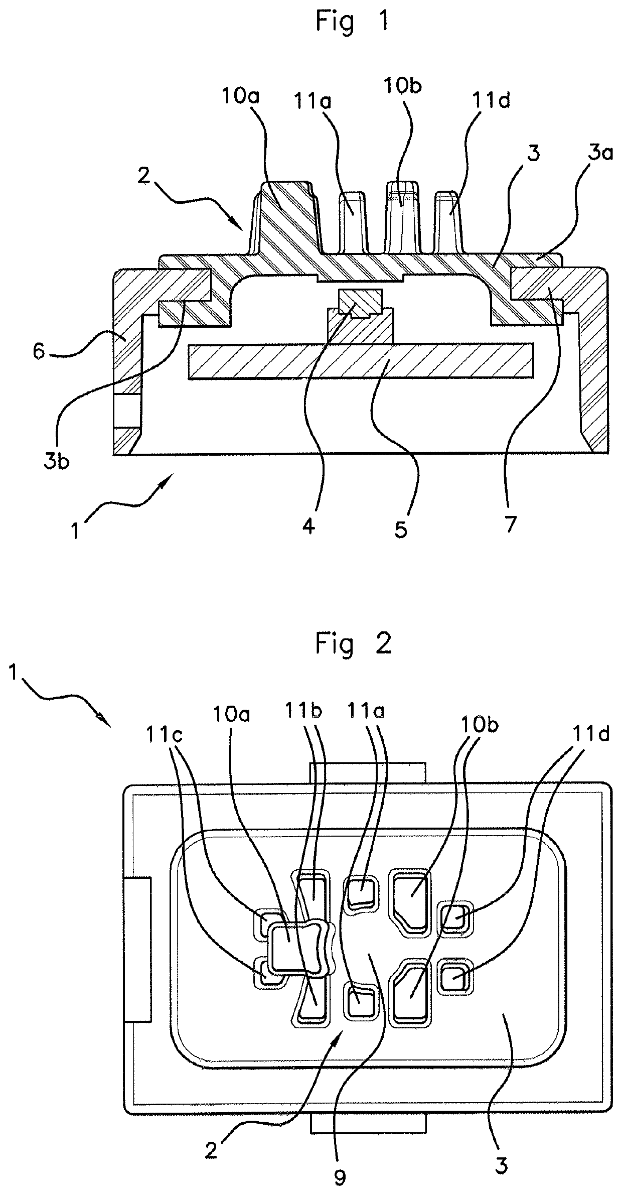
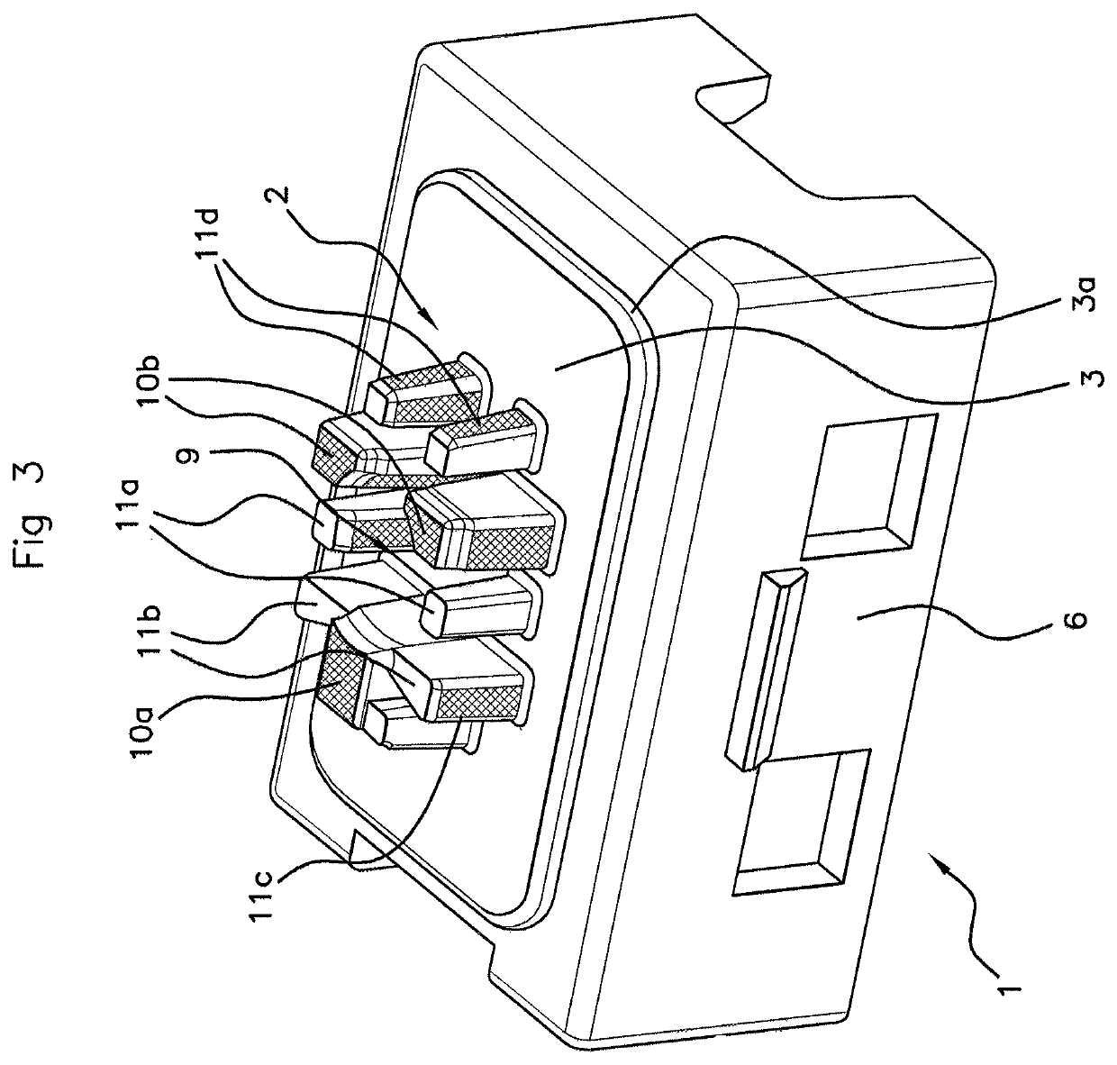
[0034]With reference to all the figures and notably to FIG. 1, an aspect of the present invention relates to an electronic push button 1 for a motor vehicle door handle, comprising an activation pattern 2 supported by a membrane 3 that is flexible in the direction of an electric switch 4 carried by a printed circuit board 5, the activation pattern 2 defining an activation surface that is pressed by an operator's finger in order to push the activation pattern 2 in the direction of the electric switch 4.

[0035]According to an aspect of the present invention, in order to allow the imposition of a lower pressing force while ensuring correct placement of the operator's finger on the activation pattern 2, and also to ensure the impermeability of the electronic push button 1, the activation pattern 2 is made up of a set of studs 10a, 10b, 11a to 11d. The studs of the set extend parallel to one another away from the electric switch 4, with the majority of the studs 10a, 11a, 10b, 11d being s...


PUM


Abstract

An electronic push button for a motor vehicle door handle, including an activation pattern supported by a membrane that is flexible in the direction of an electric switch carried by a printed circuit board, the activation pattern defining an activation surface that is pressed by an operator's finger in order to push the activation pattern in the direction of the electric switch. The activation pattern is made up of a set of studs that extend parallel to one another away from the electric switch, with the majority of the studs being spaced apart from one another, the set of studs discontinuously delimiting an outer contour of the activation surface of the electronic push button.

Description

CROSS REFERENCE TO RELATED APPLICATIONS[0001]This application is the U.S. National Phase Application of PCT International Application No. PCT / FR2018 / 050899, filed Apr. 10, 2018, which claims priority to French Patent Application No. 1754182, filed May 12, 2017, the contents of such applications being incorporated by reference herein.FIELD OF THE INVENTION[0002]The present invention relates to an electronic push button for a motor vehicle door handle, comprising an activation pattern supported by a membrane that is flexible in the direction of an electric switch. This electronic push button is intended to be disposed inside a motor vehicle door handle.[0003]The push button may serve, in association with a contactless key, to unlock a door of the vehicle when this key is located in the vicinity of the vehicle. The electronic push button serves as an alternative to locking or unlocking by a button on the key, the key then being external to the vehicle. The electronic push button is dis...

Claims


Application Information

Patent Timeline
Patent Type & Authority Patents(United States)
IPC IPC(8): E05B81/76H01H3/12H01H13/14
CPCE05B81/76H01H3/12H01H13/14H01H2229/044E05B17/0091E05B15/1635H01H13/807H01H2221/002H01H2221/078H01H2221/088
Inventor BRUNET-LUGARDON, FLORIANPERROT, PASCALCOLLET, MICHEL
Owner VITESCO TECH GERMANY GMBH
Why Eureka
Try Eureka