Staking bolt

a technology of bolts and nuts, applied in the field of bolts, can solve the problems of inability to implement fastening with nuts, difficult to completely fill the inside of the ring, etc., and achieve the effect of larger slip torqu

Active Publication Date: 2022-02-08
AOYAMA SEISAKUSHO CO LTD
View PDF20 Cites 2 Cited by
  • Summary
  • Abstract
  • Description
  • Claims
  • Application Information

AI Technical Summary

Benefits of technology

[0009]In the staking bolt according to the present invention, the minimum diameter D between respective arms of the whirl-stop protrusion formed on the bearing face of the head is larger than the outer diameter d of the ring-shaped protrusion formed on the shank, and t×(D−d) / 2, which is the longitudinal cross-sectional area A of the minimum diameter portion of the whirl-stop protrusion, is equal to or greater than the longitudinal cross-sectional area of the ring groove. For this reason, when caulked onto a metal plate, even in the minimum diameter portion of the whirl-stop protrusion, the metal material corresponding to the longitudinal cross-sectional area A can be plastically flown to completely fill the inside of the ring groove having the longitudinal cross-sectional area B. Further, since the ring-shaped protrusion formed on the bearing face of the flat head is pressed into the surface of the metal plate, even when caulked onto a thin metal plate, it is possible to obtain a slip torque larger than that of the conventional product.
[0010]When the outer diameter d1 of the portion between the ring-shaped protrusion and the external thread is equal to or less than the root diameter d2 of the external thread, the inner diameter of the nut is larger than the outer diameter d1. For this reason, a nut for fastening an object to be fastened to a shank of a staking bolt caulked onto a metal plate can be fastened to the position of a ring-shaped protrusion, so that strong fastening can be implemented even when the total thickness of the metal plate and the object to be fastened is thinner than that in the prior art.

Problems solved by technology

However, in such a conventional structure, it is not easy to completely fill the inside of the ring groove 4 with the metal material in the caulking process, and the slip torque after caulking is as low as 10 Nm or less.
Furthermore, there is a problem that the conventional staking bolt shown in Patent Literature 1 cannot tighten a nut to the vicinity of the head 1 because the head 1 and the starting position of an external thread 6 of the shank are separated, and fastening with the nut cannot be implemented unless the total thickness of the metal plate 5 and the object to be fastened is sufficiently thick.

Method used


Image

  • Staking bolt
  • Staking bolt
  • Staking bolt

Examples


example

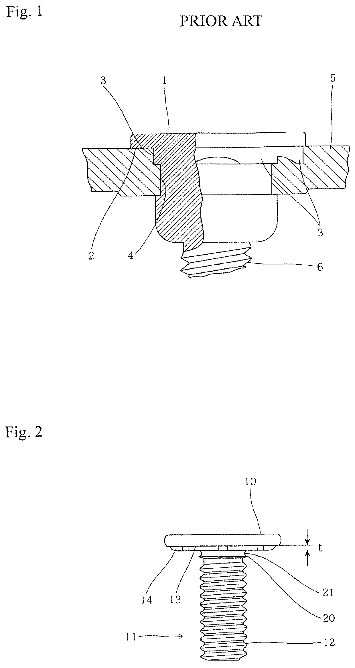
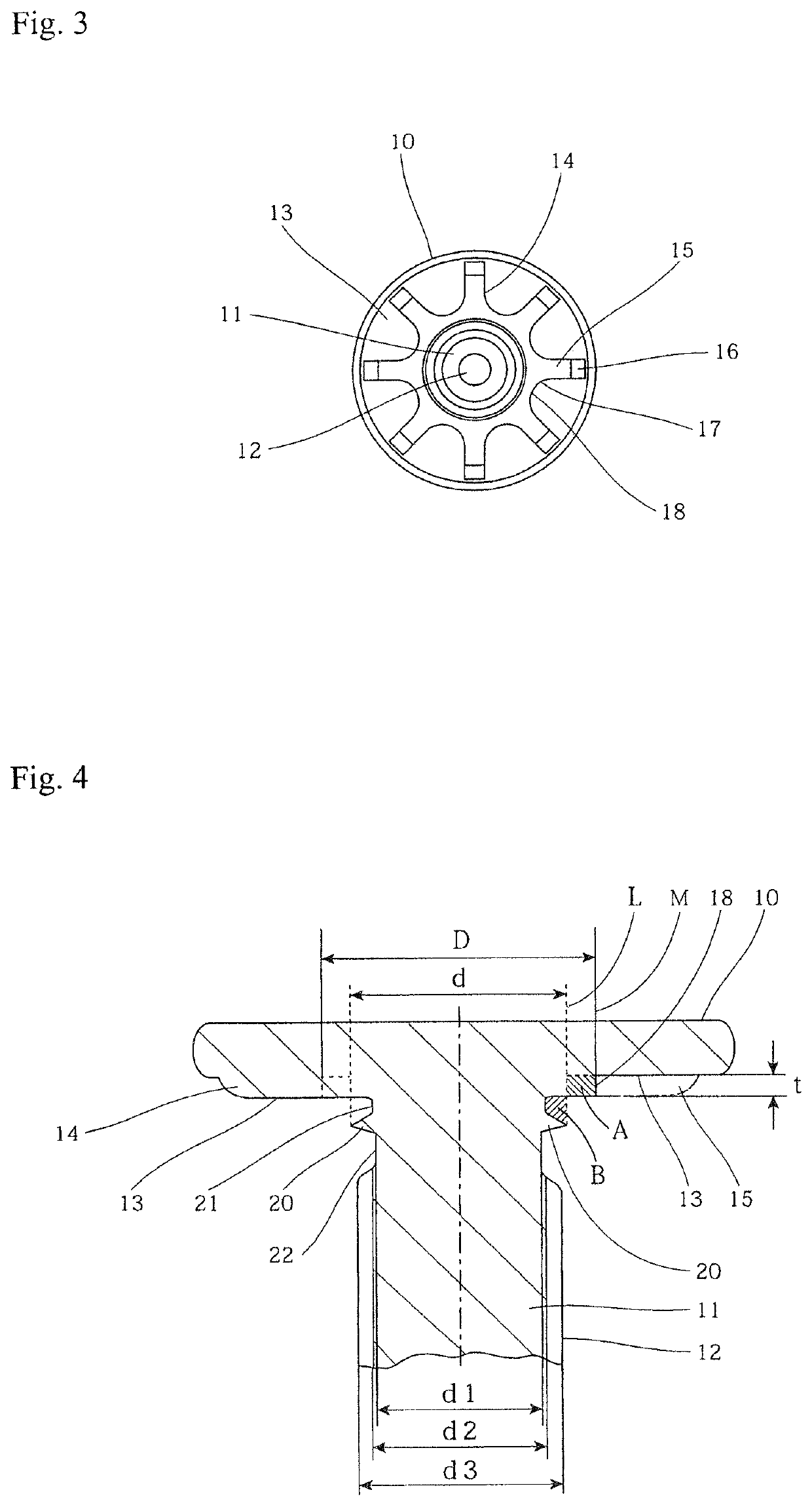
[0033]The staking bolt of the above-described embodiment was manufactured in M6 size. For the dimensions of each part, the thickness of the head is 1.5 mm, t=0.5 mm, D=7.6 mm, d=6.3 mm, d1=4.55 mm, d2=4.7 mm, d3=6.0 mm.

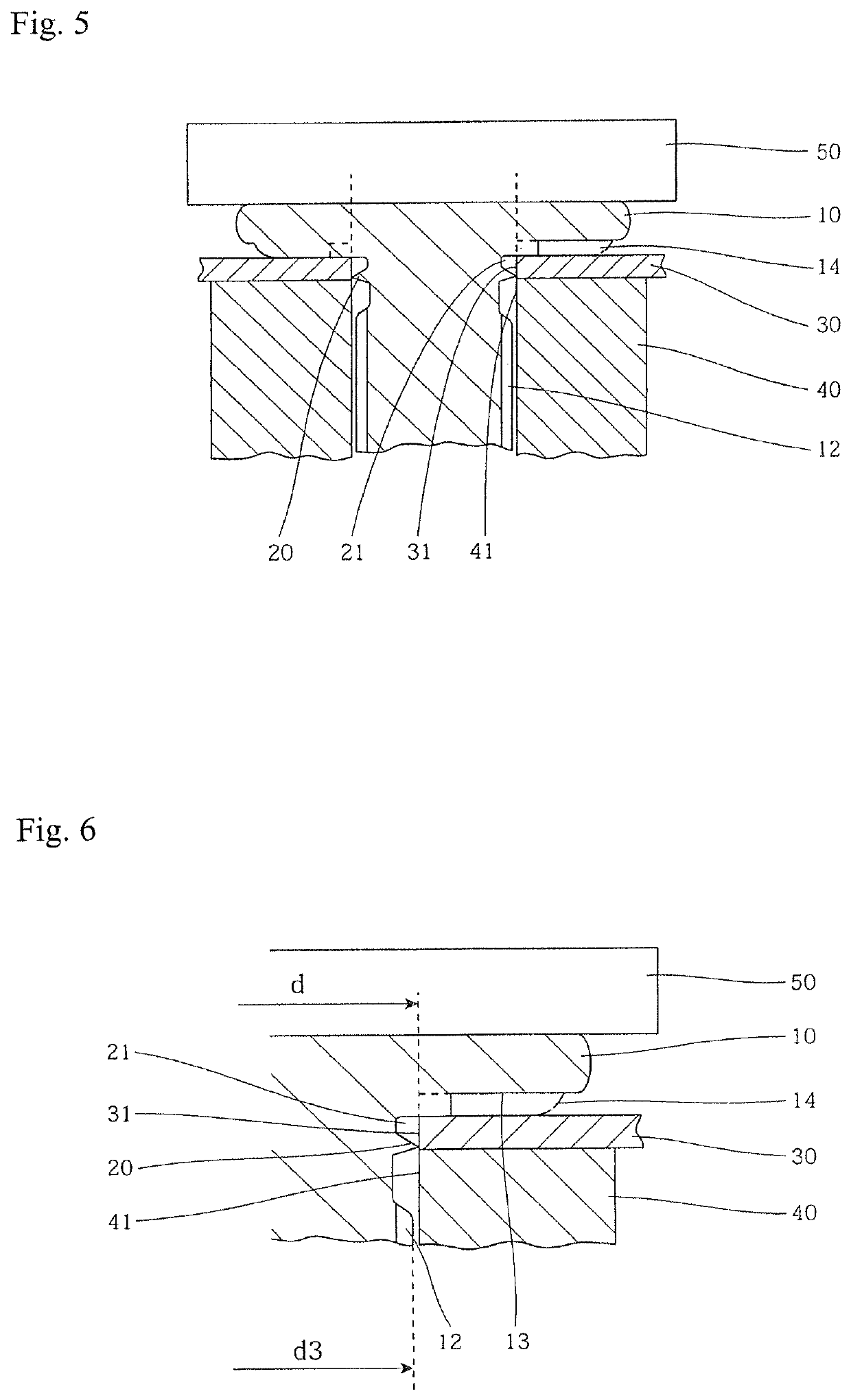
[0034]The staking bolt was inserted into the pilot hole having an inner diameter of 6.3 mm formed on a steel plate having a thickness of 1 mm, and was caulked and fixed using a die and a punch. Thereafter, when the slip torque was measured, as shown in the graph of FIG. 10, the average value of five bolts was 18 Nm.

[0035]This value was an excellently nearly twice as large as that of the slip torque of the conventional M6 size staking bolt shown as comparative data where the value was 10 Nm or less.

[0036]Moreover, fastening with the conventional M6 size staking bolt can not be implemented unless the total thickness of the metal plate and the object to be fastened is at least 3.2 mm, but secure fastening with the staking bolt having the shape of the embodiment can be im...


PUM


Abstract

The staking bolt of the present invention includes a head 10 and a shank 11 having an external thread 12. At the upper end of the shank 11, a ring-shaped protrusion 20 and a ring groove 21 located closer to the head relative to the ring-shaped protrusion 20 are formed. The head 10 is flat, and on the bearing face 13, a whirl-stop protrusion 14 having a plurality of radially extending arms 15 protrudes with a thickness of t. The minimum diameter D between respective arms 15 is larger than the outer diameter d of the ring-shaped protrusion 20, and t×(D−d) / 2 which is the longitudinal cross-sectional area A of the minimum diameter portion of the whirl-stop protrusion 14 is equal to or greater than the longitudinal cross-sectional area of the ring groove 21.

Description

CROSS REFERENCE TO RELATED APPLICATIONS[0001]This application is a continuation of International Application No. PCT / JP2017 / 043502 filed Dec. 4, 2017, which designated the United States, and claims the benefit under 35 USC § 119(a)-(d) of Japanese Application No. 2017-106171 filed May 30, 2017, the entireties of which are incorporated herein by reference.FIELD OF THE INVENTION[0002]The present invention relates to a staking bolt that is caulked and fixed to a mating metal plate and used to fasten other members.BACKGROUND OF THE INVENTION[0003]The staking bolt is a bolt that is press-fit into the pilot hole of the mating metal plate using a tool and causes the metal material to plastically flow in the ring groove formed around the shank, thereby being caulked and fixed to the metal plate. A large extraction load (extraction load in the axial direction) is required of the staking bolt. Also, since another member is fastened to the staking bolt that has been caulked and fixed using a n...

Claims


Application Information

Patent Timeline
Patent Type & Authority Patents(United States)
IPC IPC(8): F16B35/04F16B37/06F16B39/282
CPCF16B35/048F16B37/068F16B39/282F16B33/002
Inventor HOSHINO, NAOKIKOGA, KAZUHIROFUJIMOTO, YUKINORI
Owner AOYAMA SEISAKUSHO CO LTD
Why Eureka
Try Eureka