Display device and system

a technology of display device and display screen, which is applied in the field of projectors, can solve the problems of reducing the quality of the display, reducing the efficiency of the display, and reducing the amount of sunlight, so as to increase the maximum brightness and reduce the effect of waste of resources

Active Publication Date: 2022-01-25
ENVISICS LTD
View PDF31 Cites 4 Cited by
  • Summary
  • Abstract
  • Description
  • Claims
  • Application Information

AI Technical Summary

Benefits of technology

[0014]The optical system disclosed herein includes a light-selective filter. In some embodiments, the light-selective filter is a laser-line selective filter and / or a polarisation selective filter on the optical path within the HUD. This helps remove sunlight from the HUD and, in particular, reduce the amount of sunlight reaching the picture generating unit. However, these embodiments also inevitably attenuate the light forming the information content. These embodiments are therefore highly unconventional because current HUD development is heavily focused on increasing the maximum brightness which can be delivered to the driver. Achieving a commercially acceptable contrast ratio is a major problem for HUD developers. Liquid crystal displays (LCD), for example, are significantly less efficient than the holographic projector of some embodiments because they already comprise multiple optical components—such as polarisers, filters, glass plates and wave plates—which reduce intensity. These conventional technologies cannot therefore afford to lose more of the light which forms the information content. There is therefore significant technical prejudice in the field to incorporating components, such as selective filters, in the HUD which attenuate the information content because this lowers overall brightness. The selective filter / s of some embodiments are found to be very effective at reducing damage within the HUD of the present disclosure and, in particular, improving the lifetime of the light receiving surface (especially when it is made of plastic) whilst not overly reducing the achievable luminance.
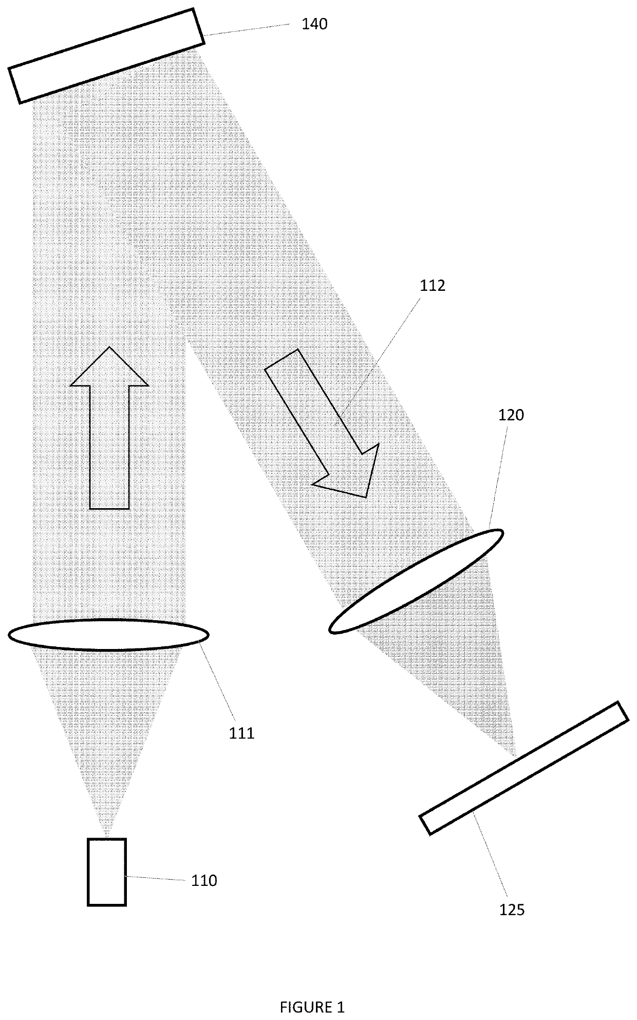
[0015]Some embodiments provide a HUD in which the picture generating unit and optical system are substantially coplanar. In summary, this is achieved by illuminating the second mirror of the optical system through the first mirror—i.e. in transmission. In some embodiments, the optical path within the optical system comprises plural interactions with the first mirror. In some embodiments, the plural interactions comprise a first interaction comprising transmission of light from the input to the second mirror and a second interaction comprising reflecting light from the second mirror to the output. Accordingly, a more compact HUD is provided and the picture generating unit may be readily shielded from sunlight in accordance with any number of designs which may be envisaged.
[0016]Some embodiments incorporating a filter or wave plate as a coating on one or both of the reflectors. These embodiments are advantageous because the filter / wave plate can be conveniently applied to one or both mirrors without introducing further complexities into the optical system. In some embodiments, a selective filter is coated on the first mirror so the unwanted ambient light is filtered from the system as close to source as possible reducing thermal concentration effects. In embodiments, the selective filtering is collectively formed on both mirrors so as to spread the thermal load.

Problems solved by technology

In some embodiments, the light receiving surface is plastic which is not a good material at dissipating heat.
A problem is that ambient light, including direct sunlight, can enter the HUD system through the aperture which is necessitated in the dashboard of the vehicle.
This can cause vailing glare which significantly reduce the quality of the display or even optical wash out of the display.
Highly concentrated sunlight within the HUD can also cause thermal damage to components of the HUD.
Using the windscreen of the vehicle as the optical combiner presents numerous optical and holographic challenges.
However, these embodiments also inevitably attenuate the light forming the information content.
Achieving a commercially acceptable contrast ratio is a major problem for HUD developers.
Liquid crystal displays (LCD), for example, are significantly less efficient than the holographic projector of some embodiments because they already comprise multiple optical components—such as polarisers, filters, glass plates and wave plates—which reduce intensity.
These conventional technologies cannot therefore afford to lose more of the light which forms the information content.
There is therefore significant technical prejudice in the field to incorporating components, such as selective filters, in the HUD which attenuate the information content because this lowers overall brightness.
That is, in accordance with this disclosure a “laser-line selective filter”, for example, allows laser-line light to propagate on the optical path described but does not allow non laser-line light to propagate any further on the optical path.

Method used


Image

  • Display device and system
  • Display device and system
  • Display device and system

Examples


Embodiment Construction

[0050]The present invention is not restricted to the embodiments described in the following but extends to the full scope of the appended claims. That is, the present invention may be embodied in different forms and should not be construed as limited to the described embodiments, which are set out for the purpose of illustration.

[0051]Terms of a singular form may include plural forms unless specified otherwise.

[0052]A structure described as being formed at an upper portion / lower portion of another structure or on / under the other structure should be construed as including a case where the structures contact each other and, moreover, a case where a third structure is disposed there between.

[0053]In describing a time relationship—for example, when the temporal order of events is described as “after”, “subsequent”, “next”, “before” or suchlike—the present disclosure should be taken to include continuous and non-continuous events unless otherwise specified. For example, the description s...


PUM


Abstract

A head-up display for a vehicle, the head-up display including a picture generating unit arranged to generate a picture on a light receiving surface; and an optical system arranged to image the picture, where the optical system includes an input arranged to receive light of the picture; an output arranged to output light forming an image of the picture; a first mirror and second mirror arranged to guide light from the input to the output along an optical path, where the optical path includes a first optical path from the input to the second mirror including a transmission through the first mirror; and second optical path from the second mirror to the output including a reflection off the first mirror.

Description

CROSS-REFERENCE TO RELATED APPLICATIONS[0001]This application claims the benefit of priority under 35 U.S.C. § 119 of United Kingdom Patent Applications nos. 1712435.5, filed Aug. 2, 2017, and 1712436.3, filed Aug. 2, 2017, each of which is hereby incorporated herein by reference in its entirety.FIELD[0002]The present disclosure relates to a projector. More specifically, the present disclosure relates to a holographic projector and holographic projection system. Some embodiments relate to a head-up display and a head-mounted display. Some embodiments relate to a method of removing unwanted light in a holographic projection system, head-up display or head-mounted display.BACKGROUND AND INTRODUCTION[0003]Light scattered from an object contains both amplitude and phase information. This amplitude and phase information can be captured on, for example, a photosensitive plate by well-known interference techniques to form a holographic recording, or “hologram”, comprising interference frin...

Claims


Application Information

Patent Timeline
Patent Type & Authority Patents(United States)
IPC IPC(8): G03H1/14G02B27/01G02B27/10G02B5/26G02B27/14G03H1/22
CPCG02B27/0103G02B5/26G02B27/01G02B27/102G02B27/145G03H1/2294G02B2027/015G02B2027/0107G02B2027/0118G03H2223/17G03H2223/24G02B5/30
Inventor CHRISTMAS, JAMIESONCOLE, ALEXANDERKARNER, MATE
Owner ENVISICS LTD
Why Eureka
Try Eureka