
Muzzle device mounting system

a technology for mounting systems and muzzles, applied in the field of muzzle devices for firearms, can solve the problems of no current design that allows for the fast and repeatable attachment of devices

Active Publication Date: 2021-12-28
OGLESBY PAUL A
View PDF14 Cites 4 Cited by
  • Summary
  • Abstract
  • Description
  • Claims
  • Application Information

AI Technical Summary

Benefits of technology

The patent text is discussing the difficulty of attaching a device (like a muzzle device or suppressor) to a barrel in a way that always works correctly and can be repeated. The technical effect of the patent is to provide a solution for this issue, allowing for better and more reliable timing between the device and the barrel.

Problems solved by technology

Unfortunately, there is no current design that allows for the fast and repeatable attachment of a device (i.e., muzzle device, suppressor, etc.) to a barrel in a manner that ensures correct and repeatable timing of the device relative to the barrel.

Method used


Image

  • Muzzle device mounting system
  • Muzzle device mounting system
  • Muzzle device mounting system

Examples


Embodiment Construction

[0096]The foregoing and other objectives, features, and advantages of the invention will be more readily understood upon consideration of the following description of the invention taken in conjunction with the accompanying drawings.

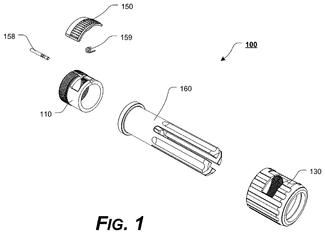
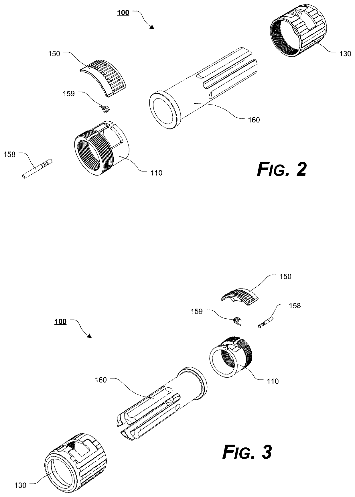
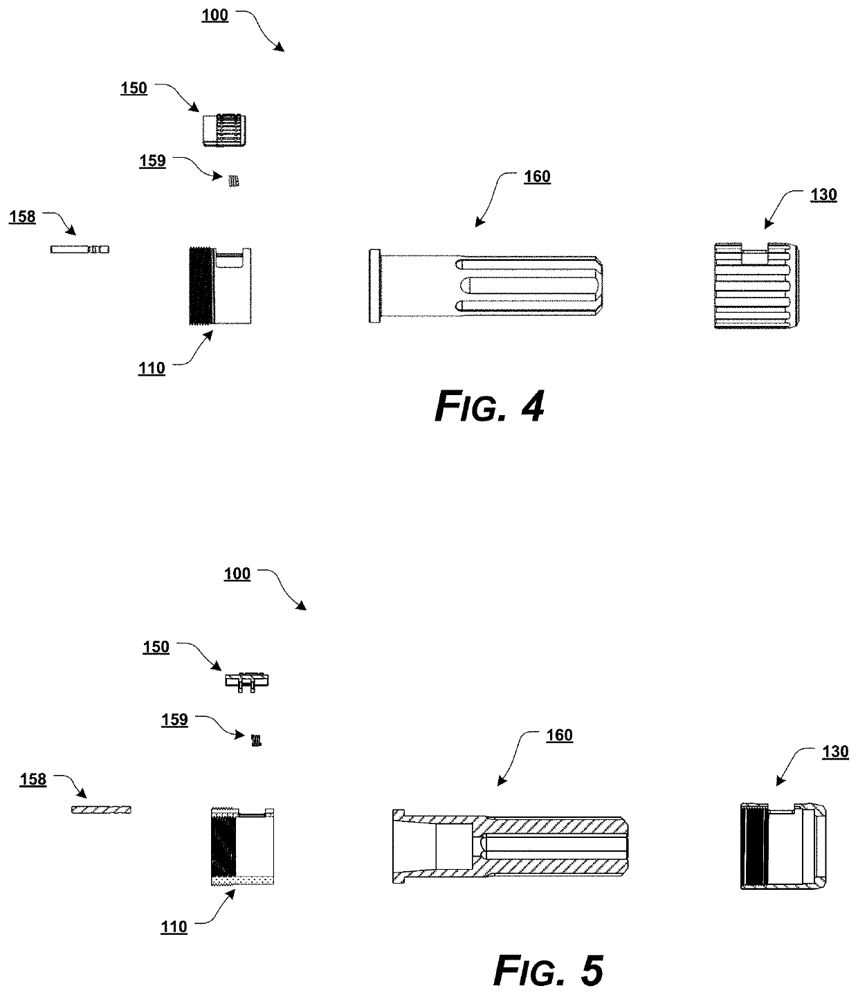
[0097]For simplicity and clarification, the design factors and operating principles of the muzzle device mounting system according to the presently disclosed systems, methods, and / or apparatuses are explained with reference to various exemplary embodiments of a muzzle device mounting system according to the presently disclosed systems, methods, and / or apparatuses. The basic explanation of the design factors and operating principles of the muzzle device mounting system is applicable for the understanding, design, and operation of the muzzle device mounting system of the presently disclosed systems, methods, and / or apparatuses. It should be appreciated that the muzzle device mounting system can be adapted to many applications where a muzzle device mounting...


PUM


Abstract

A muzzle device mounting system having an outer collar; an inner collar attached or coupled to the outer collar, wherein the outer collar is in a fixed rotational position relative to the inner collar; a muzzle device positioned at least partially between the inner collar and the outer collar, wherein the muzzle device is rotatable relative to the outer collar and the inner collar; and a pawl lever pivotably positioned relative to the outer collar and the inner collar, wherein the pawl lever includes an engagement surface for engaging one or more splines of a muzzle adapter, and wherein the pawl lever is slidable relative to the outer collar and the inner collar along a longitudinal axis of the outer collar and the inner collar.

Description

CROSS-REFERENCE TO RELATED APPLICATIONS[0001]This patent application claims the benefit of U.S. Patent Application Ser. No. 62 / 817,019, filed Mar. 12, 2019, and is a continuation-in-part of U.S. patent application Ser. No. 16 / 555,595, filed Aug. 29, 2019, which claims benefit of U.S. Patent Application Ser. No. 62 / 724,712, filed Aug. 30, 2018, and claims benefit of U.S. Patent Application Ser. No. 62 / 772,304, filed Nov. 28, 2018, the disclosures of which are incorporated herein in their entireties by reference.STATEMENT REGARDING FEDERALLY SPONSORED RESEARCH OR DEVELOPMENT[0002]Not Applicable.REFERENCE TO SEQUENCE LISTING, A TABLE, OR A COMPUTER PROGRAM LISTING COMPACT DISC APPENDIX[0003]Not Applicable.NOTICE OF COPYRIGHTED MATERIAL[0004]The disclosure of this patent document contains material that is subject to copyright protection. The copyright owner has no objection to the reproduction by anyone of the patent document or the patent disclosure, as it appears in the Patent and Tra...

Claims


Application Information

Patent Timeline
IPC IPC(8): F41A21/32
CPCF41A21/32
Inventor OGLESBY, PAUL A.
Owner OGLESBY PAUL A
Learn More