
Multi-part, sprung rail wheel

a sprung rail and multi-part technology, applied in the direction of rail-engaging wheels, wheel manufacturing, transportation and packaging, etc., can solve the problems of large friction force, large friction force, and inability to withstand the load occurring during assembly or use, so as to reduce friction and increase or wear resistance

Active Publication Date: 2021-11-30
BOCHUMER VER VERKEHRSTECHNIK GMBH
View PDF14 Cites 0 Cited by
  • Summary
  • Abstract
  • Description
  • Claims
  • Application Information

AI Technical Summary

Benefits of technology

The invention is about a rail wheel design that prevents damage to the wheel body from load peaks and reduces the risk of damage to the wheel body. This design includes a counter-bearing element that is independent of the wheel body and can absorb forces that may occur, and distribute them over a large surface area. Additionally, the invention allows for the use of various light metal materials for the wheel body without needing to consider the forces introduced by the clamping means. A circumferential shoulder is also formed to ensure a secure fit and protect the wheel body from press damage. The clamping element can be pressed onto the circumferential surface for optimal fit. The patent also suggests using molybdenum as a coating agent for good electrical transition between the clamping element and the wheel body.

Problems solved by technology

However, practical experience shows that large forces arise when the fastening bolts are tightened.
In combination with the fact that the interference fit between the wheel tyre and the wheel body is also produced concurrently during the movements, these movements lead to considerable friction forces which must be overcome by the clamping forces transmitted via the fastening screws.
Here there is a risk that the light metal material of which the wheel body consists in the region of its circumferential section, into which the threads into which the fastening screws are screwed are cut, will not withstand the loads occurring during assembly or use.
However, one disadvantage of these measures is that the clamping length of the screws required to secure the screw connection is reduced and the required diameter increases when additional thread inserts are used.
This in turn leads to a deterioration in the strength behaviour of the areas of the wheel body surrounding the receiving threads.
Likewise, when screw-in tubes are used, the possibilities of screw locking are limited, particularly by adhesive bonding.
At the same time, there is a danger that the screw-in tubes will also be unscrewed from the wheel body when the fastening screws are loosened.

Method used


Image

  • Multi-part, sprung rail wheel
  • Multi-part, sprung rail wheel
  • Multi-part, sprung rail wheel

Examples


Embodiment Construction

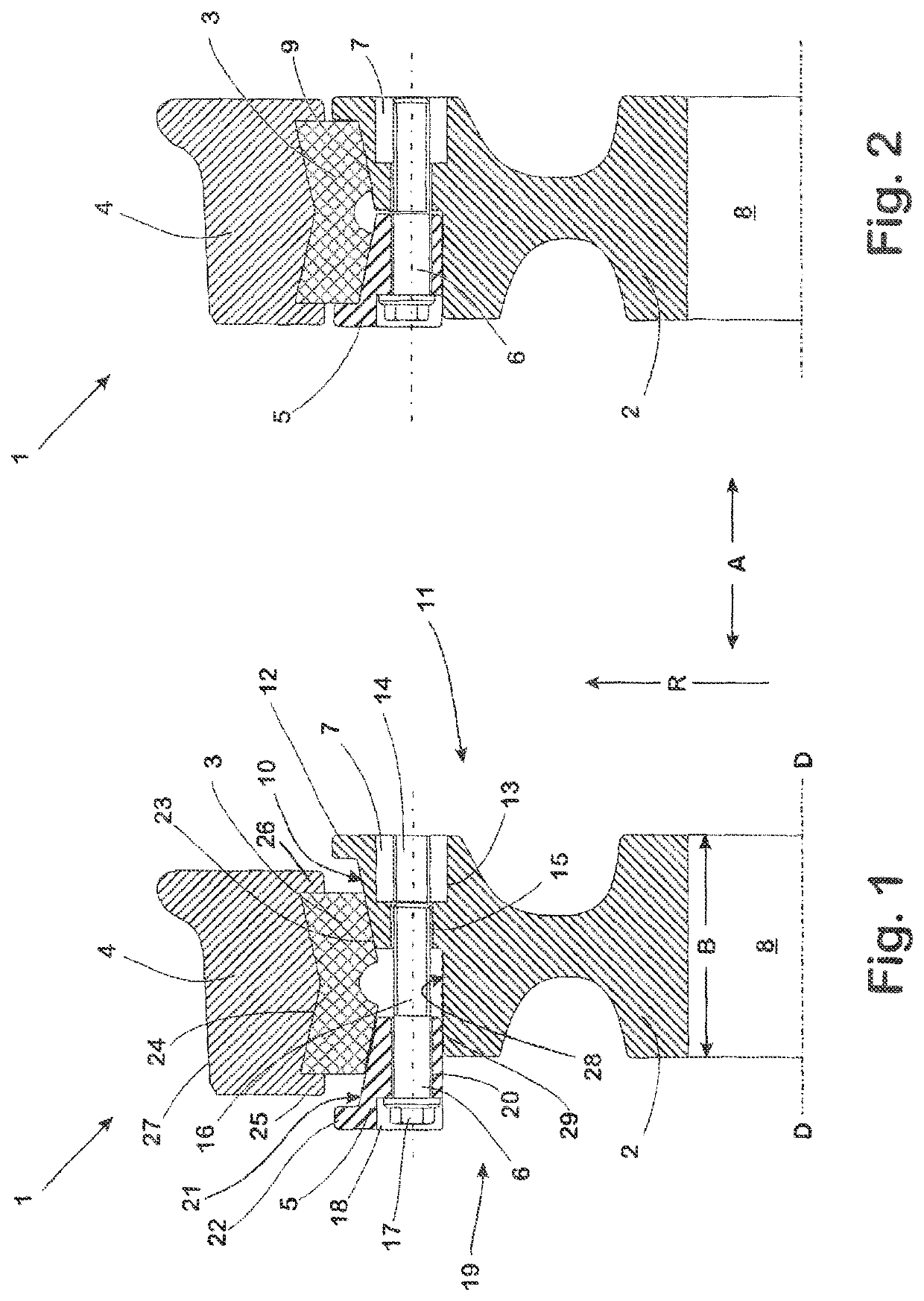
[0043]The rail wheel 1 shown in FIGS. 1 and 2 includes a wheel body 2, an elastic body 3, a wheel tyre 4, a clamping ring 5, a plurality of fastening screws 6 serving as clamping means and a counter-bearing element 7.

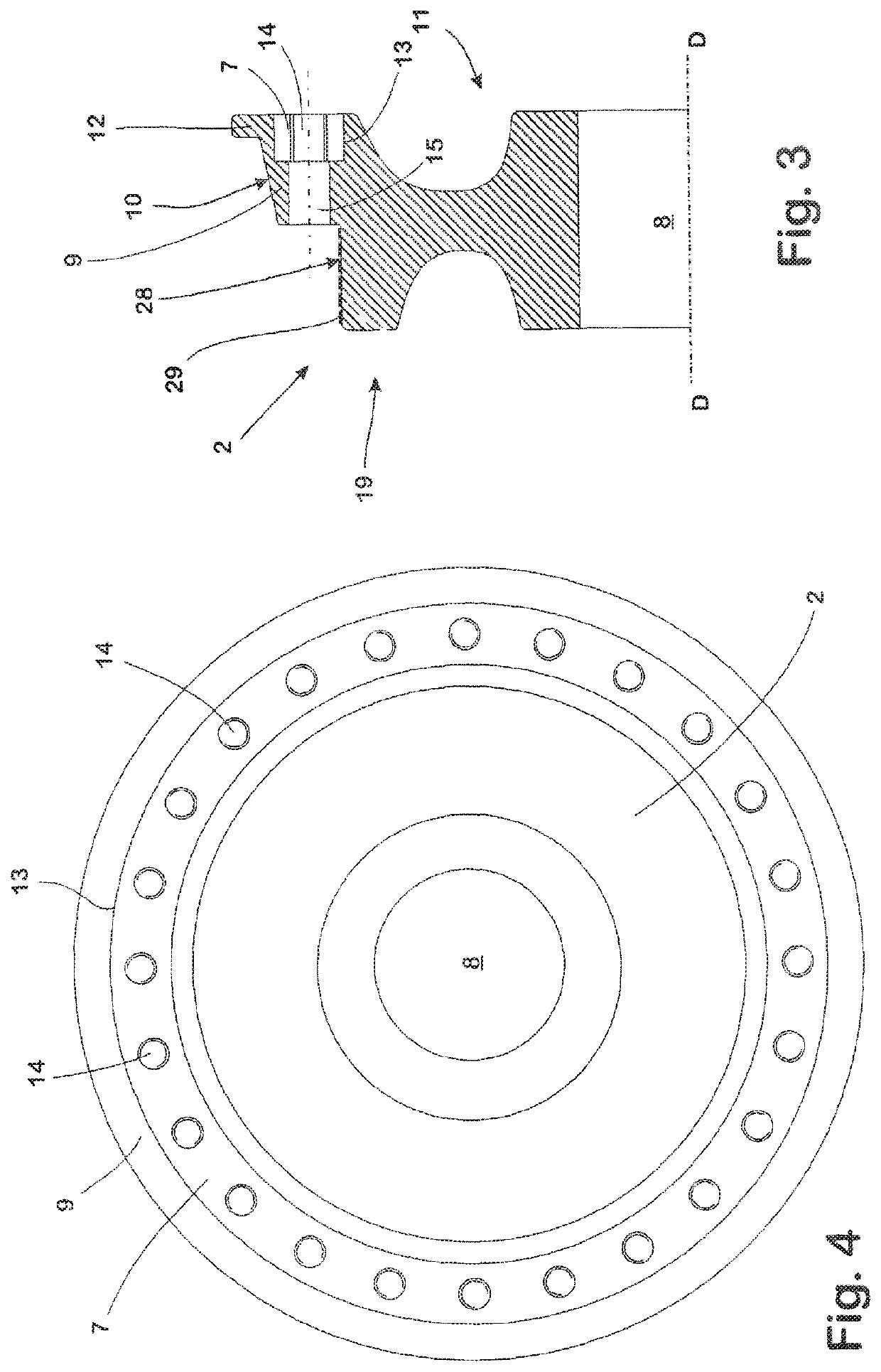
[0044]The wheel body 2 is forged from a proven aluminium material in a well-known manner. It has a central hub opening 8 through which the axis of rotation D of the rail wheel 1 runs. Around the circumference of the hub 2 there is a circumferential shoulder 9 which extends over approximately half the width B of the wheel body 2 and the circumferential surface 10 of which is inclined in the direction of the centre of the width of the hub 2 in the form of a conical ring.

[0045]At its axially outer edge assigned to one end face 11 of the wheel body 2, the circumferential shoulder 9 carries a circumferential crosspiece 12. From the end face 11, a receptacle 13 is formed in the circumferential shoulder 9 around the axis of rotation D in the form of an annular groove.

[0046]The...


PUM

PropertyMeasurementUnit
Shrinkageaaaaaaaaaa
Wear resistanceaaaaaaaaaa
Strengthaaaaaaaaaa

Abstract

The present invention relates to a multi-part rail wheel with a wheel tyre, a wheel body, an elastic body arranged between the wheel tyre and the wheel body and via which the wheel tyre is supported on the wheel body, and at least one clamping element attached to the wheel body from one end face, via which the elastic body is braced against the wheel body and the wheel tyre by clamping means acting on the wheel body, the wheel body consisting of a light metal material in the region where the clamping means act. The rail wheel guarantees secure bracing of the components with simple assembly and disassembly. This is achieved by at least one counter-bearing element being provided on the end face of the wheel body opposite the clamping element. The counter-bearing element consists of a material which has a higher strength than the wheel body material.

Description

CROSS-REFERENCE TO RELATED APPLICATIONS[0001]This application is the United States national phase of International Application No. PCT / EP2017 / 072826 filed Sep. 12, 2017, and claims priority to German Patent Application No. 10 2016 117 104.2 filed Sep. 12, 2016, the disclosure of each of which is hereby incorporated by reference in its entirety.BACKGROUND OF THE INVENTION[0002]The invention relates to a multi-part rail wheel with a wheel tyre, a wheel body and an elastic body which is arranged between the wheel tyre and the wheel body and via which the wheel tyre is supported on the wheel body, and having a clamping element which is attached to the wheel body from one end face and via which the elastic body is braced against the wheel body and the wheel tyre by means of clamping means acting on the wheel body, wherein the wheel body consists of a light metal material at least in the region against which the clamping means acts.[0003]A rail wheel of this type is known from EP 0 733 49...

Claims


Application Information

Patent Timeline
IPC IPC(8): B60B17/00B60B3/02B60B3/04
CPCB60B17/0006B60B17/0044B60B3/02B60B3/04B60B17/0055B60B17/0058B60B17/0068B60B2310/306B60B2360/102B60B2360/104B60B2360/50B60B2900/321B60B2900/711
Inventor MURAWA, FRANZ
Owner BOCHUMER VER VERKEHRSTECHNIK GMBH
Learn More