Transfer gearbox device

a gearbox and transmission technology, applied in the direction of mechanical actuated clutches, gearing details, transportation and packaging, etc., can solve the problems of high efficiency loss, and achieve the effect of efficient and economical lubrication and/or cooling

Active Publication Date: 2021-10-19
MAGNA POWERTRAIN AG & CO KG
View PDF9 Cites 0 Cited by
  • Summary
  • Abstract
  • Description
  • Claims
  • Application Information

AI Technical Summary

Benefits of technology

[0009]It is an object of the invention to improve a transfer gearbox device in this respect and, in particular, to specify a transfer gearbox device which is optimized for efficiency and has lower drag losses.
[0015]This arrangement allows both efficient and economical lubrication and / or cooling when the valve is open and stopping of the oil supply when the valve is closed. Here, the valve is preferably open when the friction clutch is closed and closed when the friction clutch is open—in particular automatically by means of a common actuating system.

Problems solved by technology

If the plates of a friction clutch of a transfer gearbox device are situated in an oil sump, even in a disconnect state, i.e. when the clutch is open, this therefore causes high efficiency losses.

Method used


Image

  • Transfer gearbox device
  • Transfer gearbox device
  • Transfer gearbox device

Examples


Embodiment Construction

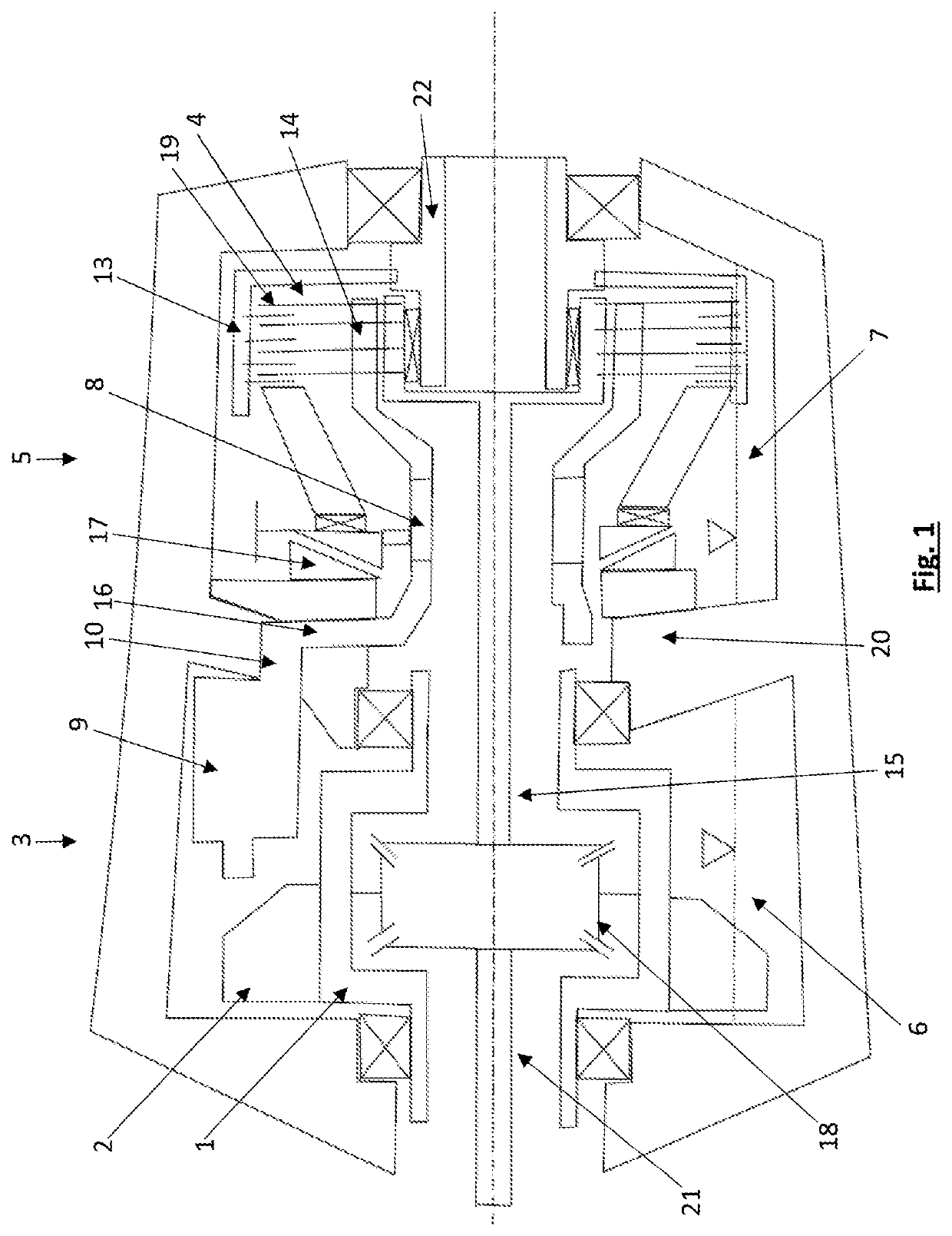
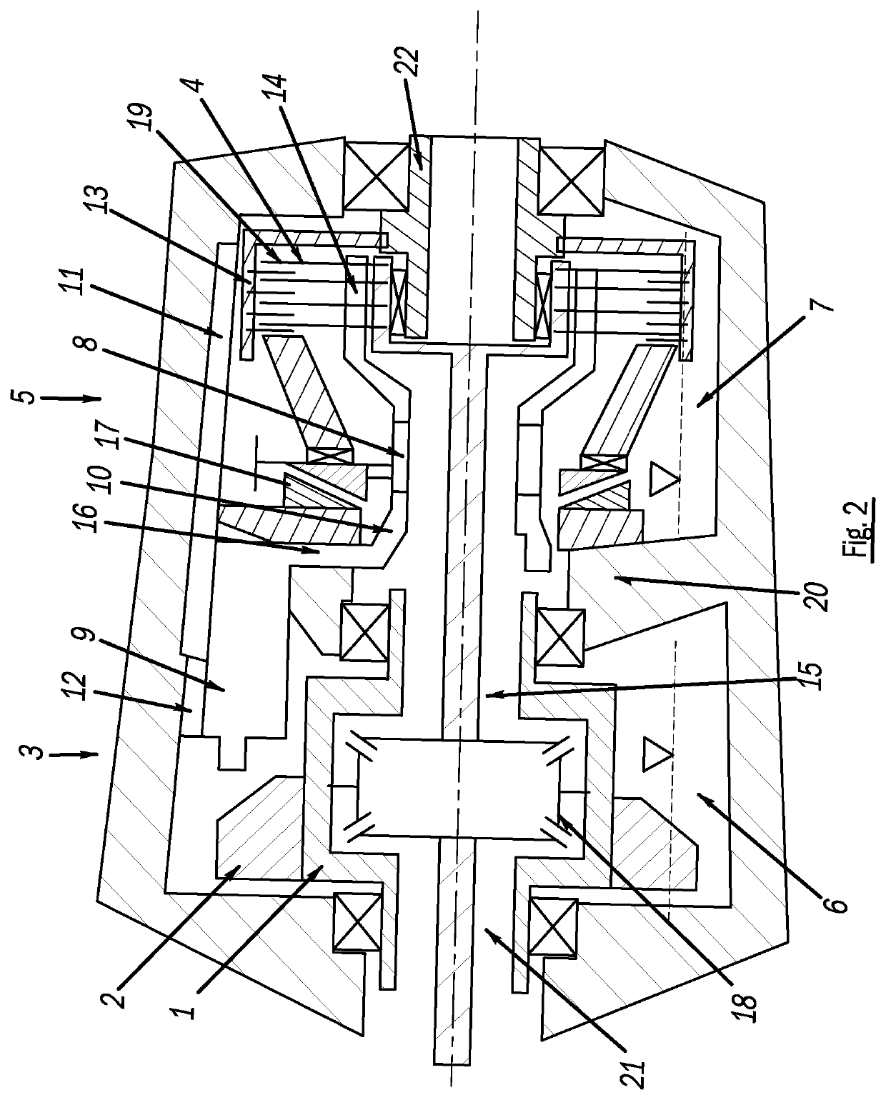
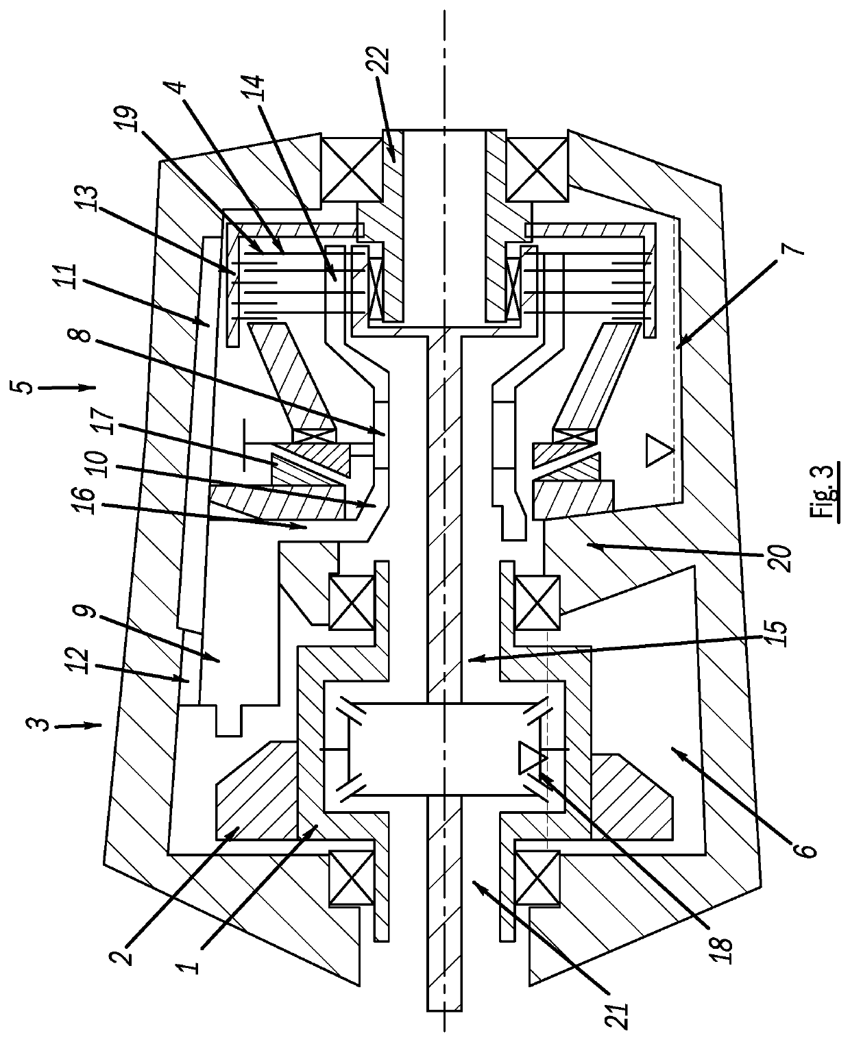
[0031]A transfer gearbox device according to the invention is illustrated in FIGS. 1-3.

[0032]The transfer gearbox device comprises a differential gear 1, having at least one crown wheel 2, as an input element of the differential gear 1, and having a first output shaft 15 and a second output shaft 21 on the two sides of the differential gear 1. The differential gear 1 is arranged in a first oil chamber 3 of the transfer gearbox device, and a friction clutch 4 is arranged in a second oil chamber 5 of the transfer gearbox device. By means of the friction clutch 4, the first output shaft 15 can be coupled to a clutch output shaft 22.

[0033]As can be seen in FIG. 1 (oil feed with the clutch 4 closed and the valve 8 open), the first oil chamber 3 comprises a first oil sump 6 and the second oil chamber 5 comprises a second oil sump 7 in the bottom region in the installed position. The oil level in the oil sumps is in each case indicated by a dotted line and a triangle resting by its tip on ...


PUM


Abstract

A transfer gearbox device, comprising a differential gear with a crown wheel in a first oil chamber, and a friction clutch in a second oil chamber. The first oil chamber comprises a first oil sump and the second oil chamber comprises a second oil sump. A valve is between the first oil chamber and the second oil chamber. When the valve is open, oil can pass via the valve out of the first oil chamber into the second oil chamber. When the valve is closed, oil cannot pass via the valve out of the first oil chamber. When the valve is open, by rotating the crown wheel, oil is conveyed by the crown wheel from the first oil sump into a first oil collector and is guided therefrom via a first oil guide and via the valve to the friction clutch cool and / or to lubricate the friction clutch.

Description

CROSS-REFERENCE TO RELATED APPLICATIONS[0001]This U.S. National Stage Patent Application claims the benefit of and priority to PCT International Patent Application Serial No. PCT / EP2018 / 059869, filed Apr. 18, 2018, which claims the benefit of and priority to DE102017208433.2, filed May 18, 2017. The entire disclosures of each of the above applications are incorporated herein by reference.FIELD OF THE INVENTION[0002]The present invention relates to a transfer gearbox device for a motor vehicle, comprising a differential gear and a friction clutch.BACKGROUND OF THE INVENTION[0003]This section provides information related to the present disclosure which is not necessarily prior art.[0004]Transfer gearbox devices for motor vehicles, by means of which an input torque can be distributed between usually two output shafts, are known per se. They can comprise a differential gear for infinitely variable distribution of the input torque between two output shafts and a friction clutch for coupl...

Claims


Application Information

Patent Timeline
Patent Type & Authority Patents(United States)
IPC IPC(8): F16H57/04F16D13/72B60K17/346F16D13/74
CPCB60K17/346F16H57/0483F16D13/72F16D13/74F16H57/045F16H57/0423F16H57/0457F16H57/0473F16H57/0409F16H57/0424F16H57/0435F16H57/0445F16H57/0453
Inventor LEGL, LUKAS
Owner MAGNA POWERTRAIN AG & CO KG
Why Eureka
Try Eureka