Acousto-optic gyroscopes

a gyroscope and optical technology, applied in the field of acoustooptic gyroscopes, can solve the problems of large released mass, limited output bandwidth, and mvgs being vulnerable to shock, and achieves wide bandwidth operation, low noise level, and large unreleased mass

Active Publication Date: 2021-09-07
CARNEGIE MELLON UNIV
View PDF8 Cites 0 Cited by
  • Summary
  • Abstract
  • Description
  • Claims
  • Application Information

AI Technical Summary

Benefits of technology

[0004]Disclosed herein is an Acousto-Optic Gyroscope (AOG), which has the theoretical capability of addressing all the major issues encountered in MVGs or miniaturized OGs. The AOG is based on the concept of the Surface Acoustic Wave Gyroscope (SAWG), in which the Coriolis force detection is performed optically instead of acousto-electrically. The use of SAW resonators enables the realization of a large unreleased mass and wide bandwidth operation. The optical sensing of the strain induced by the Coriolis force (via the acousto-optic effects) provides for extremely low noise levels, high sensitivity, and stable readout. In addition, the optical detection method significantly simplifies the electronic readout. The Coriolis-induced strain is mapped to a change in the effective index of the optical waveguide through the acousto-optic effect. Different photonic phase sensing techniques can be used to detect the index change such as a Mach-Zehnder Interferometer (MZI) operated in the push pull operation or a racetrack (RT) resonator. Herein is described an implementation of the AOG in a lithium niobate on insulator (LNOI) substrate, which was selected because of its unique acoustic and photonic properties. The Scale Factor, SF, of a gyroscope is defined as the ratio of the output voltage to the input rotation. The derivation of the SF for the AOG and a comparison the two aforementioned phase sensing techniques are shown below. Various embodiments and a method of fabrication are presented. A theoretical analysis verified experimentally is also discussed.

Problems solved by technology

The need for a large released mass makes MVGs vulnerable to shock.
Because most MVGs operate at few kHz with quality factors >1,000, their output bandwidth is limited to mHz for frequency matched operation unless complex bandwidth extension techniques are used.
Furthermore, the low operation frequency makes the gyroscope susceptible to environmental vibrations.
Unfortunately, miniaturization and power scaling of these implementations are challenging.

Method used


Image

  • Acousto-optic gyroscopes
  • Acousto-optic gyroscopes
  • Acousto-optic gyroscopes

Examples


Embodiment Construction

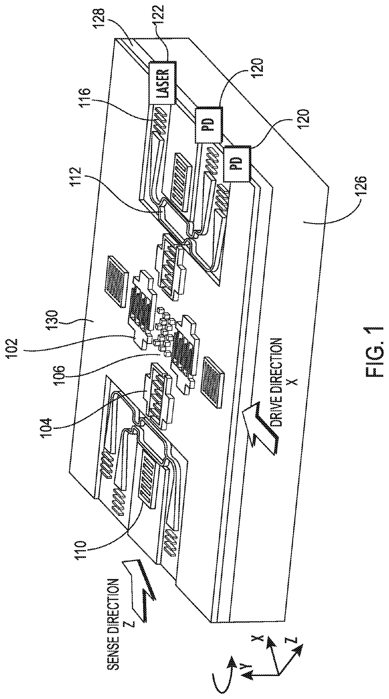
[0023]FIG. 1 depicts a schematic view of the AOG and offers an overview of its principle of operation. Two orthogonal SAW resonators 102, 104, are provided with metallic pillars 106 placed at the center acting as the moving mass, Mp, of the gyroscope. A SAW standing wave pattern is established along the drive (X) direction. The pillars 106 are placed inside the cavity at the anti-nodes of the SAW standing wave pattern, that is, at the location of the maximum x-directed velocity. The pillars 106 are driven longitudinally with vibration velocity, vp. When out-plane rotation, Ωz, is applied, Coriolis force, Fc, is induced on the vibrating pillars 106 in the direction orthogonal to both the input rotation direction and the drive vibration direction. The Coriolis force can be expressed as:

Fc=−2MpΩz×vp  (1)

[0024]The pillars are arranged in a checkerboard configuration such that their constructive interference establishes a secondary SAW in the sense (Z) direction. For Rayleigh SAW mode, t...


PUM


Abstract

An Acousto-Optic Gyroscope (AOG) consisting of a photonic integrated device embedded into two inherently matched piezoelectric surface acoustic wave (SAW) resonators sharing the same acoustic cavity is disclosed. The micromachined strain-based AOG uses the effective index of the optical waveguide due to the acousto-optic effect rather than conventional displacement sensing.

Description

RELATED APPLICATIONS[0001]This application claims the benefit of U.S. Provisional Application No. 62 / 606,676, filed Oct. 3, 2017.GOVERNMENT INTEREST[0002]This invention was made with government support under a contract from the Defense Advanced Research Projects Agency (DARPA) entitled Precise Robust Inertial Guide for Munitions (PRIGM)-Advanced Inertial Micro Sensor (AIMS) program (Award No. N66001-16-1-4025). The U. S. Government has certain rights in the invention.BACKGROUND OF THE INVENTION[0003]Existing gyroscopes for inertial navigation systems are based on either bulky mechanical implementations or large volume and high power Optical Gyroscopes (OGs). MEMS vibratory gyroscopes (MVGs) are an interesting alternative but have exhibited limitations on various fronts. The need for a large released mass makes MVGs vulnerable to shock. Because most MVGs operate at few kHz with quality factors >1,000, their output bandwidth is limited to mHz for frequency matched operation unless ...

Claims


Application Information

Patent Timeline
Patent Type & Authority Patents(United States)
IPC IPC(8): G01C19/5698G01H9/00G10K11/36
CPCG01C19/5698G01H9/004G10K11/36
Inventor PIAZZA, GIANLUCAMAHMOUD, MOHAMEDMAHMOUD, ASHRAFCAI, LUTONGKHAN, MD SHOFIQUL ISLAMMUKHERJEE, TAMALBAIN, JAMES
Owner CARNEGIE MELLON UNIV
Why Eureka
Try Eureka