
Cardiac treatment system and method

a treatment system and heart technology, applied in the field of medical devices for treating heart diseases and valvular dysfunction, can solve the problems of fatigued patients and discomfort, achieve the effects of reducing fatigue, improving blood flow from the heart, and advantageously advancing the implant structure to the hear

Active Publication Date: 2021-09-07
DIAXAMED LLC
View PDF38 Cites 0 Cited by
  • Summary
  • Abstract
  • Description
  • Claims
  • Application Information

AI Technical Summary

Benefits of technology

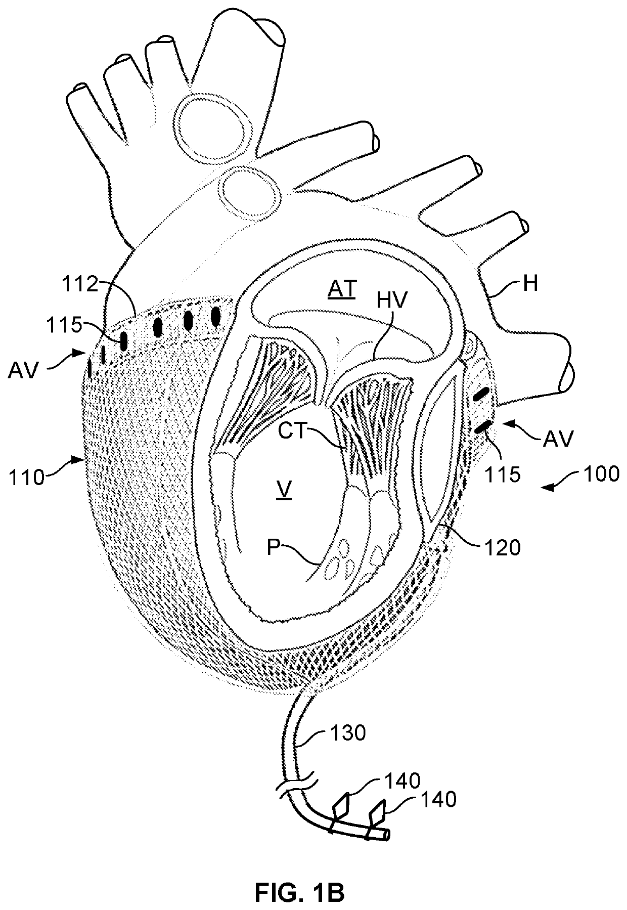
[0014]These and other embodiments described herein may provide one or more of the following benefits. First, some embodiments include an implant structure having a combination of components that operate to contemporaneously apply forces for supporting or deformation different targeted regions of the heart. For example, the implant structure of particular embodiments of the system described can be configured to contemporaneously apply a localized pressure to a defined area of the posterior lateral surface of the heart while also applying a restraining force of to the ventricle walls of the heart and (optionally) a compressive supporting force to the atrial-ventricular groove of the heart.
[0015]Second, some embodiments of the system or method described herein can be used to treat various heart conditions, including but not limited to functional mitral valve regurgitation (“FMR”), tricuspid valve regurgitation, congestive heart failure, or a combination thereof. Upon implantation, implantation structure can apply forces for supporting or deformation regions of the heart in a manner that eliminates or reduces the symptoms of these conditions and that improves blood flow from the heart.
[0016]Third, some embodiments of the system or method described herein can include a delivery device configured to advantageously advanced the implant structure to the heart through a relatively small opening of a selected intercostal space proximate to the apex of the heart. Optionally, each delivery device can be configured as a disposable, single-use instrument that is pre-loaded with the implant structure and packaged in a sterilized kit. As such, the clinician can simply select a delivery device bearing the selected size of implant structure (pre-installed on a barrel of the delivery device by during manufacture or assembly) from a plurality of delivery devices in a hospital inventory. After the implant structure in implanted, the delivery device can be conveniently discarded along with other disposables from the operating room.
[0017]Fourth, in some embodiments, the implant structure can be arranged on the delivery device in a predetermined orientation relative to the handle of the delivery device. In such circumstances, the fillable bladder of the implant structure may be predisposed for advancement along a targeted side of the heart (e.g., a posterior side) when the handle of the delivery device is held in a selected position external to the opening in the chest, thereby assisting the clinician in aligning the fillable bladder with the targeted surface region of the heart.

Problems solved by technology

In time, the heart cannot supply an adequate amount of blood, resulting in a patient that is fatigued and in discomfort.

Method used


Image

  • Cardiac treatment system and method
  • Cardiac treatment system and method
  • Cardiac treatment system and method

Examples


Embodiment Construction

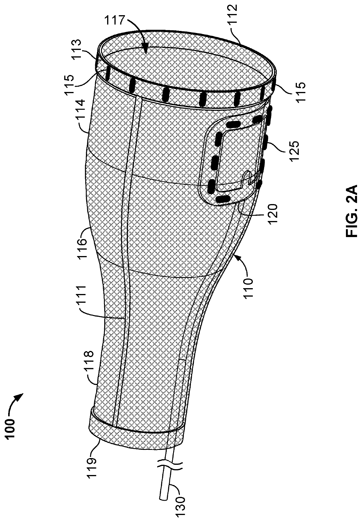
[0059]Referring to FIGS. 1A-1B, some embodiments of a system or method described herein include an implant structure configured to be positioned around the exterior of an epicardial surface of a heart H. Such an implant 100 can be used, for example, to treat various heart conditions, including but not limited to FMR, tricuspid valve regurgitation, congestive heart failure, or a combination thereof. For example, in the embodiment depicted in FIG. 1B, the implant 100 can include a fillable bladder 120 coupled to a mesh body 110 at a specific location to exert a localized pressure on the posterior lateral surface of the heart H to thereby deflect the “P2” portion of the posterior leaflet of the mitral valve to treat FMR. The combined components of the implant 100 can be configured to apply supporting or deformation forces to multiple targeted regions of the heart H in a manner that supports the ventricle walls of the heart, particular valve structures of the heart, and (optionally) atr...


PUM


Abstract

Devices and methods for providing localized pressure to a region of a patient's heart to improve heart functioning, including: (a) a jacket made of a flexible biocompatible material, the jacket having an open top end that is received around the heart and a bottom portion that is received around the apex of the heart; and (b) at least one inflatable bladder disposed on an interior surface of the jacket, the inflatable bladder having an inelastic outer surface positioned adjacent to the jacket and an elastic inner surface such that inflation of the bladder causes the bladder to deform substantially inwardly to exert localized pressure against a region of the heart.

Description

CROSS REFERENCE TO RELATED APPLICATIONS[0001]This application claims the benefit of U.S. Application Ser. No. 62 / 558,027, filed Sep. 13, 2017. The disclosure of the prior application is considered part of and is incorporated by reference in the disclosure of this application.TECHNICAL FIELD[0002]The present disclosure relates to medical devices for treating heart diseases and valvular dysfunction, including valvular regurgitation.BACKGROUND OF THE INVENTION[0003]Various compression-style systems currently exist for treating heart diseases and conditions such as congestive heart disease and valvular dysfunction. These systems typically involve either: (a) jackets that are placed around the heart to limit heart expansion to treat congestive heart disease, or (b) bands that are placed around the heart with fillable chambers to exert localized pressure to re-form the shape of heart valves, for example to minimize valve leakage.[0004]An example of the former is found in U.S. Published Pa...

Claims


Application Information

Patent Timeline
Patent Type & Authority Patents(United States)
IPC IPC(8): A61F2/24A61M60/40A61M60/268
CPCA61F2/2481A61M60/268A61M60/40A61F2002/2484A61M60/289A61M60/839A61M60/191A61M60/468
Inventor HJELLE, AARON J.SHIPKOWITZ, TANYA
Owner DIAXAMED LLC
Learn More