
Medical device to remove an obstruction from a body lumen, vessel or organ

a technology of a distal end and a gripping tool, which is applied in the field of selectively bendable remote access gripping tools, can solve the problems of preventing oxygen and nutrients from being delivered, affecting the function so as to facilitate the proper positioning of the distal end, facilitate the possibility of further options for users

Active Publication Date: 2021-08-10
KOVARIK CARTER J +1
View PDF218 Cites 0 Cited by
  • Summary
  • Abstract
  • Description
  • Claims
  • Application Information

AI Technical Summary

Benefits of technology

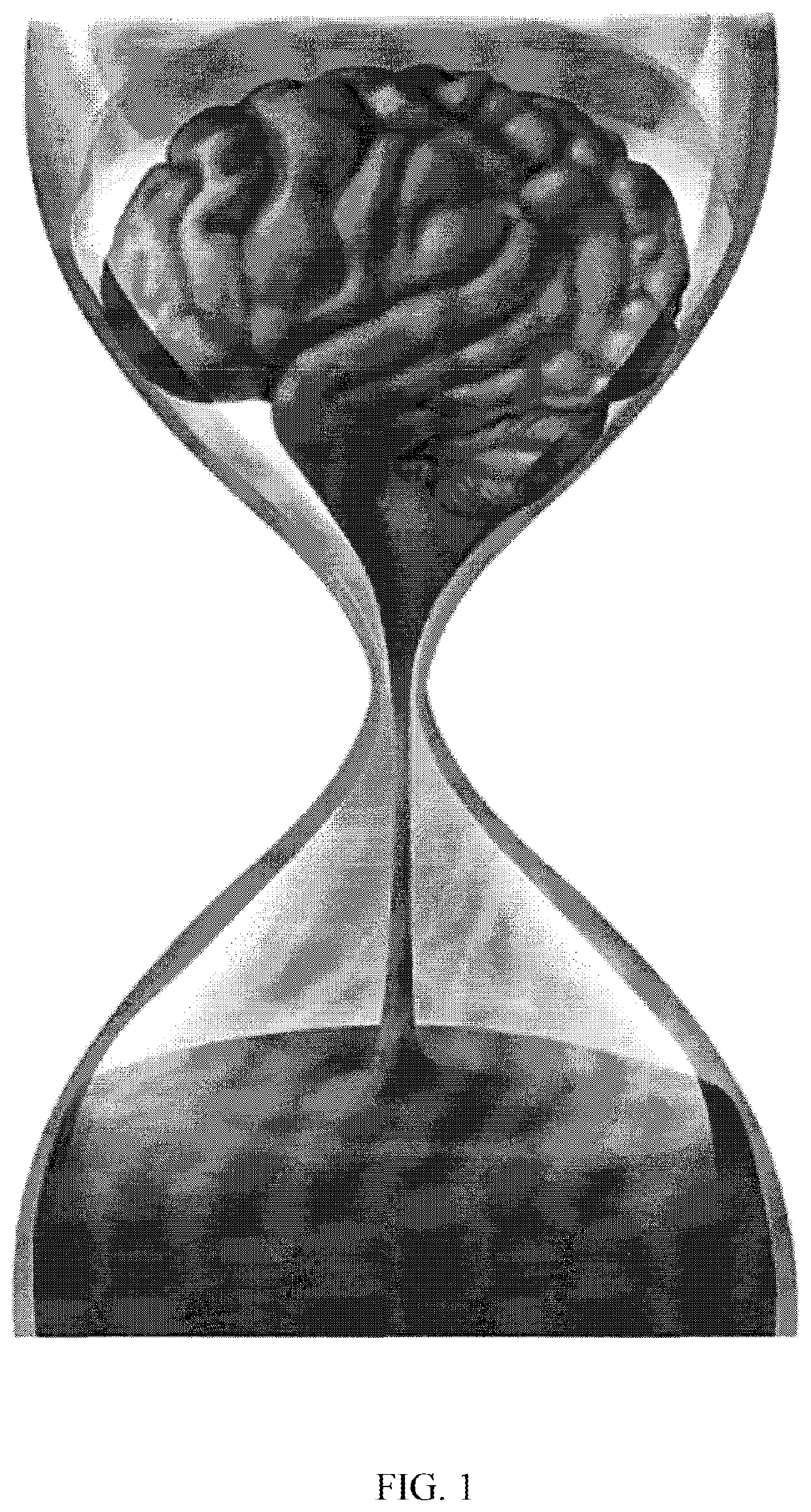
The device allows for rapid and safe capture and removal of blood clots, reducing the risk of further embolization and vessel damage, and can be used in small vessels, potentially saving brain tissue by shortening treatment times and minimizing complications during stroke intervention.

Problems solved by technology

Once lodged, the thrombus occludes flow along the vessel downstream of the blockage, thus arresting blood flow to the downstream blood vessel and causing the stroke.
The blockage disrupts blood flow, which prevents oxygen and nutrients from being delivered to their intended locations.
Tissue distal to a blood clot that is deprived of oxygen and nutrients can no longer function properly.
For every minute that treatment is delayed, additional cellular death of critical tissue can occur.
Current technology for blood flow restoration, for example for treating cerebral arteries occluded by thrombi, can often take hours to reestablish flow in the artery, and can lead to unintended complications.
Apparatus and methods for treating cerebral thrombi are often ineffective or only partially effective at resolving thrombus removal, and may result in distal embolization or embolization of uninvolved arteries.
These devices often fail to capture all of a thrombus, can damage vessel walls distal of a thrombus, can be difficult to maneuver, can unintentionally dislodge portions of a thrombus prior to capture, and / or can take significant amounts of time to restore blood flow.
Dislodgment of portions of the thrombus, referred to as secondary emboli, often cause complications because the secondary emboli may travel downstream and occlude other vessels or arteries.
Retraction of the basket into the sheath results in the cage collapsing and entrapping the object in the basket.
The grasping legs are typically formed of elastic wires with insufficient rigidity to reliably hold retrieved objects and thus, the legs may deform and drop the objects during operation.

Method used


Image

  • Medical device to remove an obstruction from a body lumen, vessel or organ
  • Medical device to remove an obstruction from a body lumen, vessel or organ
  • Medical device to remove an obstruction from a body lumen, vessel or organ

Examples


Embodiment Construction

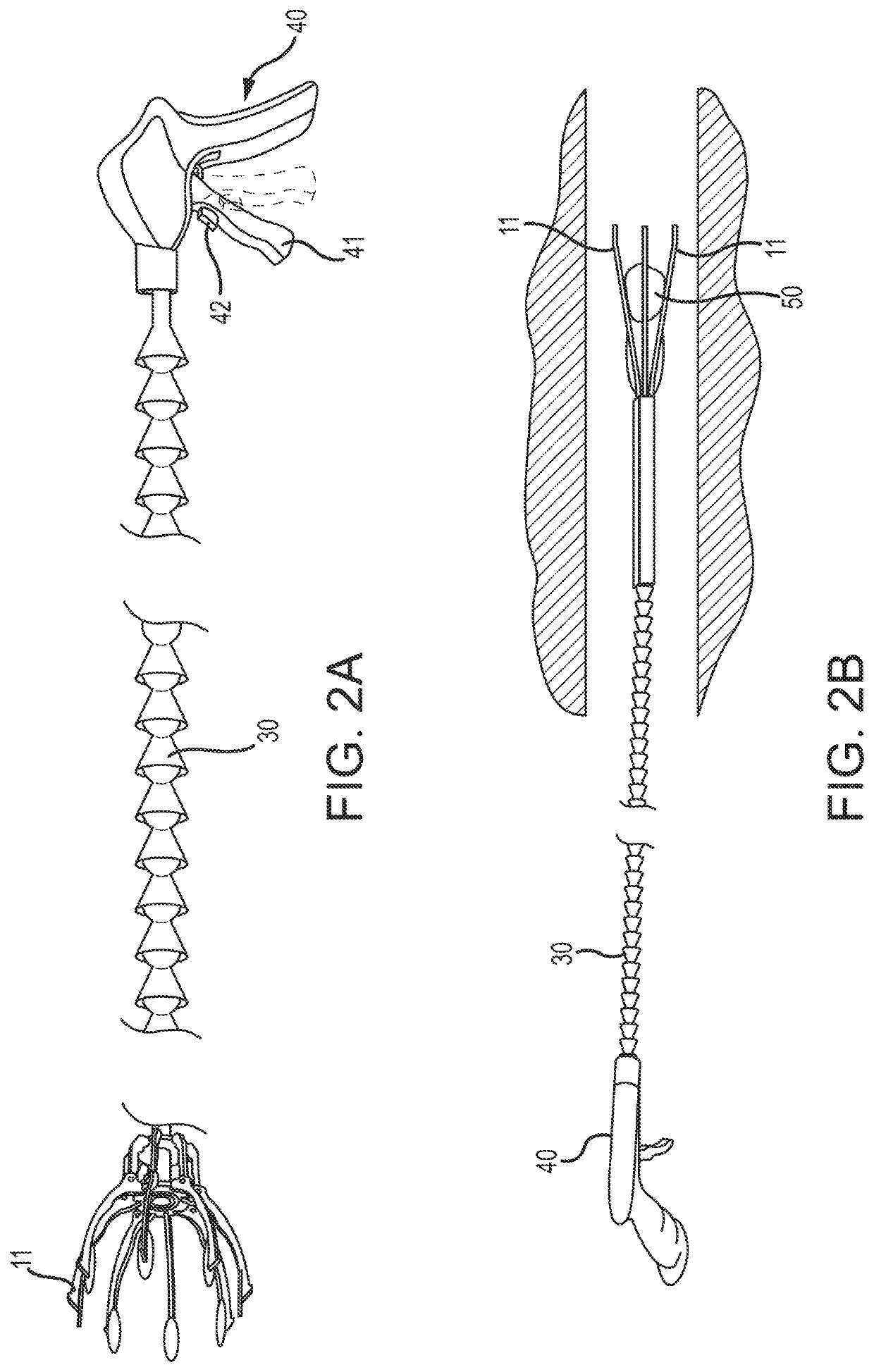
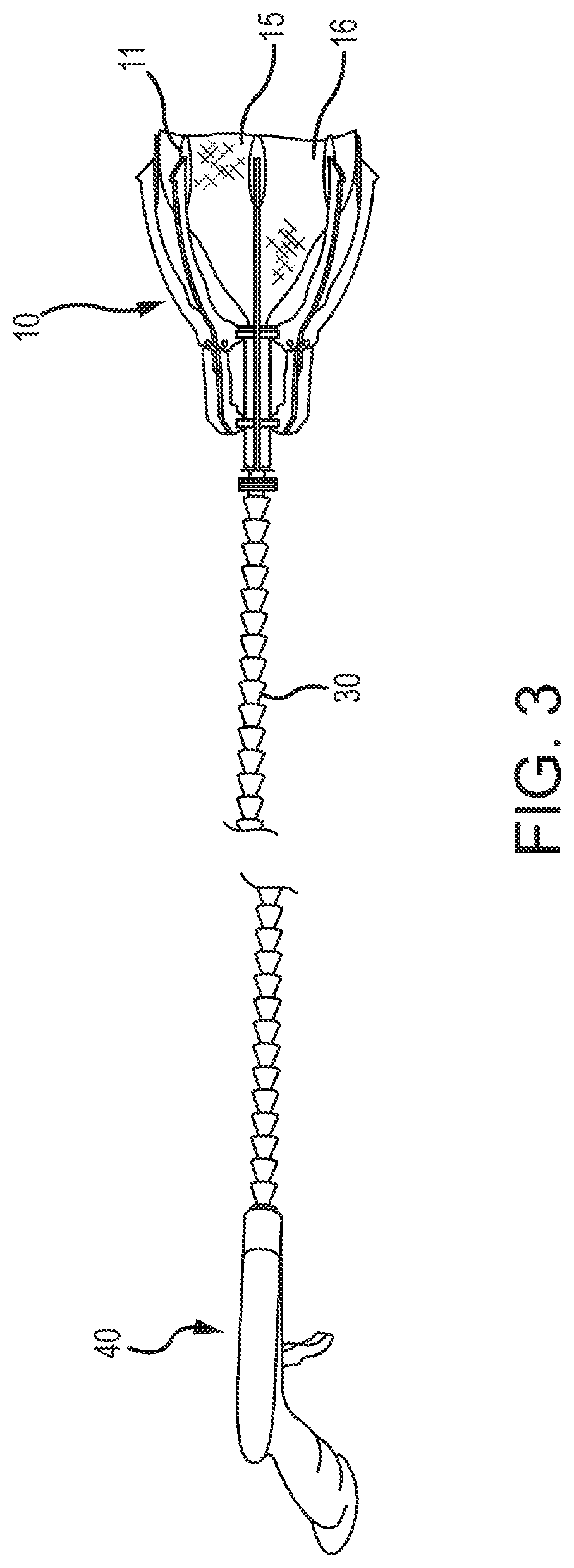
[0066]It will be understood that the disclosed embodiments are merely exemplary of the invention that may be embodied in various and alternative forms. The figures are not necessarily to scale, some features may be exaggerated or minimized to show details of particular components. Therefore, specific structural and functional details disclosed herein are not to be interpreted as limiting, but merely as a representative basis for teaching one skilled in the art to variously employ the present invention. For the following description, the actuatable tool head assembly is described as a gripper having a jaw assembly 11. It is understood, however, that any type of actuatable tool head assembly may be used.

[0067]As disclosed in the figures, various embodiments of the present invention generally comprise a hand-held gripping device having a jaw portion (indicated generally at 10) comprising a pair of jaws 11a, 11b and a handle portion (indicated generally at 40) spaced apart by a selectiv...


PUM


Abstract

A hand-held gripping device that allows a surgeon to reach interior portions of a person's anatomy, includes a gripping portion having a pair of jaws and / or nets movable relative to each other between fully clamped and fully opened positions thereof, a handle portion spaced apart from the jaw portion by a bendable central portion that is hollow and corrugated, with a cord extending therethrough.

Description

RELATED APPLICATIONS[0001]This application is a continuation-in-part application of U.S. patent application Ser. No. 15 / 431,044, filed on Feb. 13, 2017 (now U.S. Pat. No. 10,226,266, issued Mar. 12, 2019), which is a continuation-in-part of U.S. patent application Ser. No. 14 / 822,238, filed on Aug. 10, 2015 (now U.S. Pat. No. 9,901,245, issued Feb. 27, 2018), which is a continuation-in-part application of U.S. patent application Ser. No. 14 / 684,000, filed on Apr. 10, 2015 (now U.S. Pat. No. 9,592,066, issued Mar. 14, 2017), which is a continuation-in-part application of Ser. No. 14 / 539,021, filed on Nov. 12, 2014 (now U.S. Pat. No. 9,932,980, issued Dec. 5, 2017), which is a continuation-in-part of U.S. patent application Ser. No. 14 / 535,539, filed on Nov. 7, 2014 (now issued U.S. Pat. No. 9,095,127, issued Aug. 4, 2015), which is a continuation-in-part of U.S. patent application Ser. No. 14 / 290,207, filed on May 29, 2014 (now issued U.S. Pat. No. 8,985,659, issued Mar. 24, 2015, wh...

Claims


Application Information

Patent Timeline
Patent Type & Authority Patents(United States)
IPC IPC(8): A61B17/221A61B1/06A61B1/05A61B17/32A61B17/3201A61B17/00A61B17/22A61B90/30A61B90/00
CPCA61B17/221A61B1/05A61B1/0684A61B17/22031A61B17/3201A61B17/320016A61B90/30A61B90/361A61B2017/00296A61B2017/00323A61B2017/00353A61B2017/00876A61B2017/2215A61B2017/22035A61B2090/3616
Inventor KOVARIK, CARTER J.KOVARIK, JOSEPH E.
Owner KOVARIK CARTER J
Learn More