
Sample distribution system and method for distributing samples

a distribution system and sample technology, applied in the field of sample distribution system, can solve the problems of invalid previous samples or results, not fully detached, etc., and achieve the effect of saving time, avoiding collisions between pipetting units and containers, and ensuring safety

Active Publication Date: 2021-07-27
INTEGRA BIOSCI CORP
View PDF33 Cites 1 Cited by
  • Summary
  • Abstract
  • Description
  • Claims
  • Application Information

AI Technical Summary

Benefits of technology

[0031]In another further development, the sensor unit can be configured to monitor the minimum clearance height of the pipetting unit over at least one of the containers, and in another further development of the method according to the invention, the minimum clearance height of the pipetting unit over at least one of the containers can be monitored. The monitoring of the clearance height is advantageous, because the necessarily present sensor unit can assume another additional monitoring function. As a result, collisions between the pipetting unit and containers can be safely avoided. Furthermore, it is possible to limit the clearance height to a minimum, i.e. depending on whether pipette tips have been attached to the pipetting unit or not, the pipetting unit can be moved at a greater or lesser height over the containers. It is thus possible to optimize the travel path of the pipetting unit such that the shortest possible travel path can be implemented with the greatest safety. This saves time for the individual pipetting procedures, which, in the case of numerous pipetting procedures that must be carried out in a test, results in a large and clearly noticeable efficiency.
[0032]Furthermore, each container can have a separate dedicated sensor unit. As a result, it is possible to optimize the clearance height, because the containers may be of different heights, thus requiring a separate monitoring for each container in order to obtain the minimum clearance height.

Problems solved by technology

Furthermore, one of the common problems associated with disposing of the pipette tips is that, although they are released from the connecting section, they are not fully detached because of static electricity.
If contaminated pipette tips come in contact with the samples, all previous samples or results must be regarded as invalid.

Method used


Image

  • Sample distribution system and method for distributing samples
  • Sample distribution system and method for distributing samples

Examples


Embodiment Construction

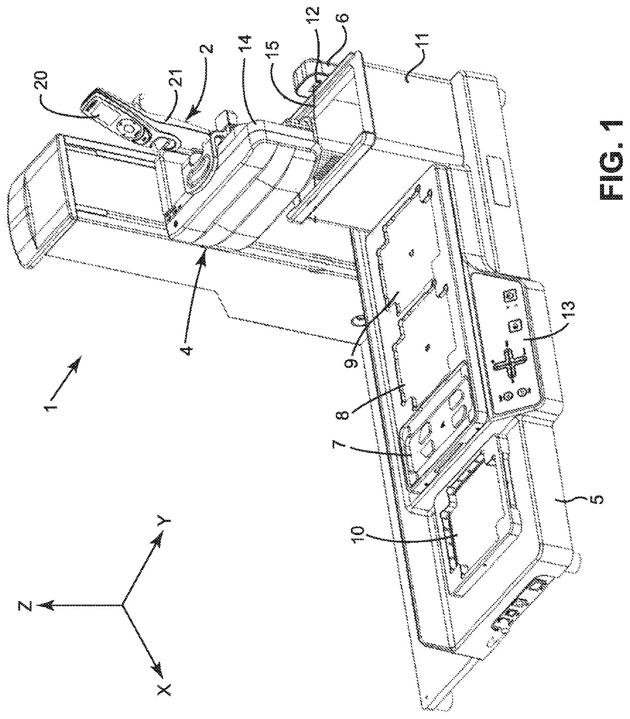
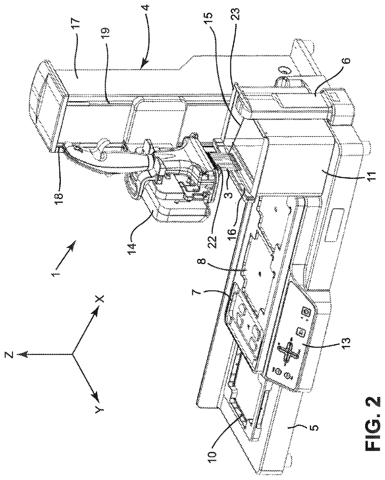
[0061]An exemplary embodiment of a sample distribution system 1 is shown in FIGS. 1 and 2 from different perspectives. The substantial components thereof are a regulator 4 and a base plate 5. The regulator 4 has an L-shaped carrier arm 14 for receiving a pipetting unit 2. The pipetting unit 2 is a multi-channel pipette that can accommodate a total of 12 pipette tips 3 in the embodiment shown therein. Furthermore, the regulator 4 has a mast-like guide arm 17 with guide slots 18, 19. The carrier arm 14 can be raised or lowered in relation to the sample containers, not shown therein. In other words, a movement clearance is created by the guide slots 18, 19 of the regulator 4 in conjunction with the carrier arm 14 that runs parallel to the Z-axis. It is also possible to move the regulator 4 on a sliding surface on the base plate 5 along the X-axis. The regulator 4 is guided thereby in a recess, not visible in FIG. 1. The regulator consequently allows the pipetting unit 2 to be raised or...


PUM

PropertyMeasurementUnit
diameteraaaaaaaaaa
clearance heightaaaaaaaaaa
shapeaaaaaaaaaa

Abstract

A sample distribution system 1 has a regulator 4 for receiving a pipetting unit 2 that has at least one exchangeable pipette tip 3, wherein the regulator 4 is configured to change the position of the pipetting unit 2 in relation to a base plate 5, and to detect the presence or absence of pipette tips 3 with a sensor unit 12. According to the invention, the sensor unit 12 is a photoelectric sensor, in particular a reflection photoelectric sensor, with a detection range. The sensor unit 12 and the pipetting unit 2 can also move in relation to one another, in order to determine the presence of a pipette tip 3, if the pipette tip is in the detection range of the sensor unit 12.

Description

FIELD OF THE INVENTION[0001]The invention relates to a sample distribution system using a sensor unit to detect e.g. the presence or absence of pipette tips.BACKGROUND OF THE INVENTION[0002]Sample distribution systems are known from the prior art and typically used in laboratories. These sample distribution systems usually work with pipettes used for dosing fluids. There are automatic pipette systems and handheld and / or manual pipettes. All of these devices have a sample container in which liquid samples are usually received, and from which these can be dispensed.[0003]Samples can be received and dispensed, for example, in that a vacuum is generated in the sample container for receiving a sample, and a pressure is generated for dispensing the sample. Piston stroke pipettes have a moving piston for this, in which an air column is located between the sample and the piston. When the piston moves in a first direction, the piston compresses the air column, and when the piston moves in th...

Claims


Application Information

Patent Timeline
Patent Type & Authority Patents(United States)
IPC IPC(8): G01N35/10B01L3/02G01N21/552
CPCG01N35/1065B01L3/0237B01L3/0275G01N21/553G01N35/109B01L2200/143B01L3/0213G01N35/00584G01N35/10G01N2035/00772
Inventor MÜLLER, GARRYSTÄDLER, ANDREAS
Owner INTEGRA BIOSCI CORP
Learn More