Stabilizer for vehicle, and shot peening jig for stabilizer

a stabilizer and vehicle technology, applied in the direction of abrasive blasting machines, manufacturing tools, transportation and packaging, etc., can solve the problems of minute corrosion pits, uneven stress distribution in each section in circumferential direction, and the depth of the pit may exceed the depth of compressive residual stress

Active Publication Date: 2021-07-13
NHK SPRING CO LTD
View PDF25 Cites 0 Cited by
  • Summary
  • Abstract
  • Description
  • Claims
  • Application Information

AI Technical Summary

Benefits of technology

[0009]Accordingly, an object of the present invention is to provide a vehicle stabilizer having a stress distribution which is suitable for the durability of bend sections, and a shot peening jig capable of subjecting stabilizers to shot peening efficiently.
[0011]According to the present invention, a stabilizer having a distribution of compressive residual stress which is suitable to increase the durability of bend sections can be obtained, and the durability of the stabilizer can be improved.

Problems solved by technology

However, in the radial cross sections of the bend sections, the distribution of stress arising in each section in a circumferential direction is not uniform.
For example, because of a bounding stone touching the lower surface of the stabilizer or a snow-melting agent adhering to the lower surface of the stabilizer while the vehicle is traveling, a minute corrosion pit may arise.
If this corrosion pit grows to a certain degree, the depth of the pit may exceed the depth of compressive residual stress.
Thus, if the depth of compressive residual stress in the lower surface of the stabilizer is equal to the depth of compressive residual stress in the upper surface of the stabilizer, the lower surface of the stabilizer may be weak in strength.
Thus, the operation efficiency is low, and there is also a problem in that the shot peening device cannot be efficiently used.

Method used


Image

  • Stabilizer for vehicle, and shot peening jig for stabilizer
  • Stabilizer for vehicle, and shot peening jig for stabilizer
  • Stabilizer for vehicle, and shot peening jig for stabilizer

Examples


Embodiment Construction

[0026]A stabilizer according to one embodiment of the present invention will be described hereinafter with reference to FIG. 1 to FIG. 3.

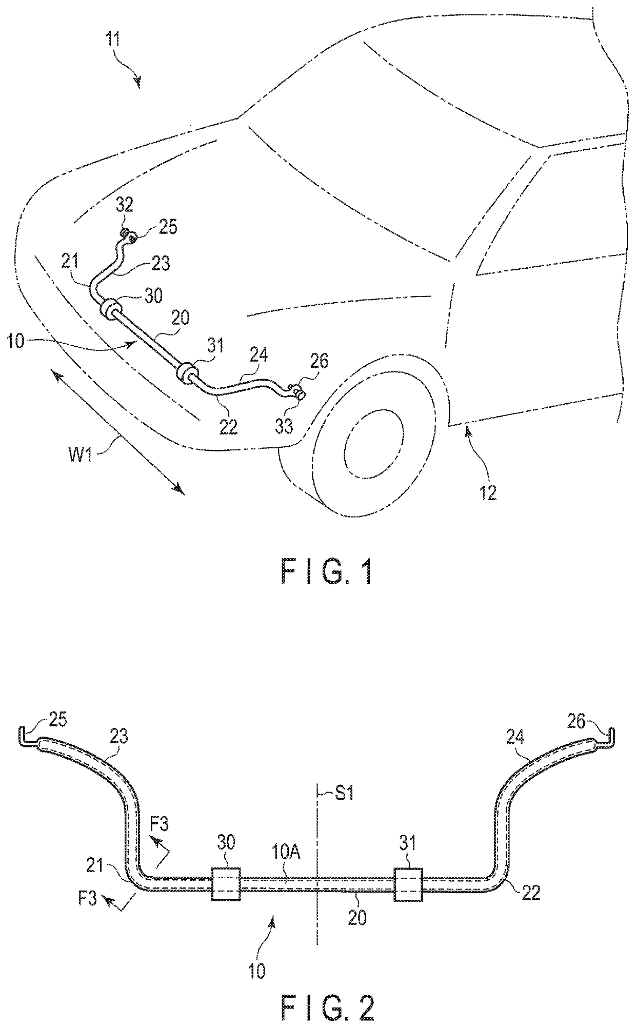
[0027]FIG. 1 shows part of a vehicle 11 comprising a stabilizer 10. FIG. 2 is a plan view of the stabilizer 10. The stabilizer 10 is placed in a suspension mechanism part of the vehicle 11. The stabilizer 10 includes a torsion section 20, a pair of bend sections 21 and 22, and a pair of arms 23 and 24. The torsion section 20 extends in a width direction (direction indicated by an arrow W1 in FIG. 1) of a vehicle body 12 of the vehicle 11. The bend sections 21 and 22 are continuous with both ends of the torsion section 20. The arms 23 and 24 are continuous with the respective bend sections 21 and 22. The stabilizer 10 is formed by a bending machine. A material of the stabilizer 10 is rod-shaped spring steel. The spring steel is selected from types of steel that can improve in strength by heat treatment such as quenching. Because the stabilizer 10 is...


PUM

PropertyMeasurementUnit
right angleaaaaaaaaaa

Abstract

A stabilizer includes bend sections. With respect to positions in a circumferential direction of a radial cross section of each of the bend sections, a center of an inside of a bend is defined as 0°, and a center of an outside of the bend is defined as 180°. The bend sections each include a bend interior section located at 0°, a bend exterior section located at 180°, a first side section located at 90°, and a second side section located at 270°. The bend interior section has compressive residual stress from a surface to a first depth. The bend exterior section has compressive residual stress to a second depth. The first side section has compressive residual stress to a third depth. The second side section has compressive residual stress to a fourth depth.

Description

CROSS-REFERENCE TO RELATED APPLICATIONS[0001]This application is a Continuation Application of PCT Application No. PCT / JP2017 / 025777, filed Jul. 14, 2017 and based upon the prior Japanese Patent Application No. 2016-022865, filed Feb. 9, 2016, the entire contents of all of which are incorporated herein by reference.BACKGROUND OF THE INVENTION1. Field of the Invention[0002]The present invention relates to a vehicle stabilizer which is placed in a suspension mechanism part of a vehicle such as a car, and a shot peening jig for the stabilizer.2. Description of the Related Art[0003]The stabilizer placed in the suspension mechanism part of the vehicle is formed of a steel pipe or a solid rod-shaped steel material. The stabilizer comprises a torsion section, a pair of arms continuous with both ends of the torsion section via bend sections, and the bend sections formed between the torsion section and each of the arms. The torsion section extends in a width direction of the vehicle. At dist...

Claims


Application Information

Patent Timeline
Patent Type & Authority Patents(United States)
IPC IPC(8): B60G21/055B24C1/10B24C3/10
CPCB60G21/055B24C1/10B24C3/10B60G2202/135B60G2206/427B60G2206/72B60G2206/8403B60G2206/8103
Inventor SAKURAI, YASUHARUKOSHITA, YOSHIHIRONISHIKAWA, AKIHIKOOTANI, AKIFUMI
Owner NHK SPRING CO LTD
Why Eureka
Try Eureka