Deer hunting decoy

Active Publication Date: 2017-12-26
MCWHORTER PAULA
View PDF18 Cites 4 Cited by
  • Summary
  • Abstract
  • Description
  • Claims
  • Application Information

AI Technical Summary

Benefits of technology

The patent describes a decoy for hunting deer that includes a hollow central post with a sidewall and an opening at the top. The central post has an axle bar with a W-shaped or V-shaped activation bar and an angled U-shaped tension bar. The axle bar has a front and a rear face, with the front face having a flexible cover with a tail flap attached to it. The cover has an opening at the top and is supported by a resilient band. The cover also has a first frame and a second frame to stabilize the first and second faces. The cover is made of a flexible material, such as textile or foam, and may be stiffened by joining it to a stiffening substrate. The technical effects of this design include a more lifelike decoy that can be easily attached to the ground and a flexible cover that can be opened and closed to expose the tail flap.

Problems solved by technology

Such methods often are deficient because the deer do not approach the hunters location within shooting distance without additional visual confirmation of the presence of other animals.
The decoy is cumbersome with its molded plastic body and lacks head and neck features to simulate a doe or a buck.
The electronic mechanism adds complexity.
Notwithstanding various attempts to create deer decoys that are effective in attracting the attention of deer, the current decoys either fail to simulate the movement of a deer tail to a sufficient degree to attract and maintain the attention of deer, fail to permit a hunter to control their movement, and / or require burdensome mounting structure.

Method used


Image

  • Deer hunting decoy
  • Deer hunting decoy
  • Deer hunting decoy

Examples


Embodiment Construction

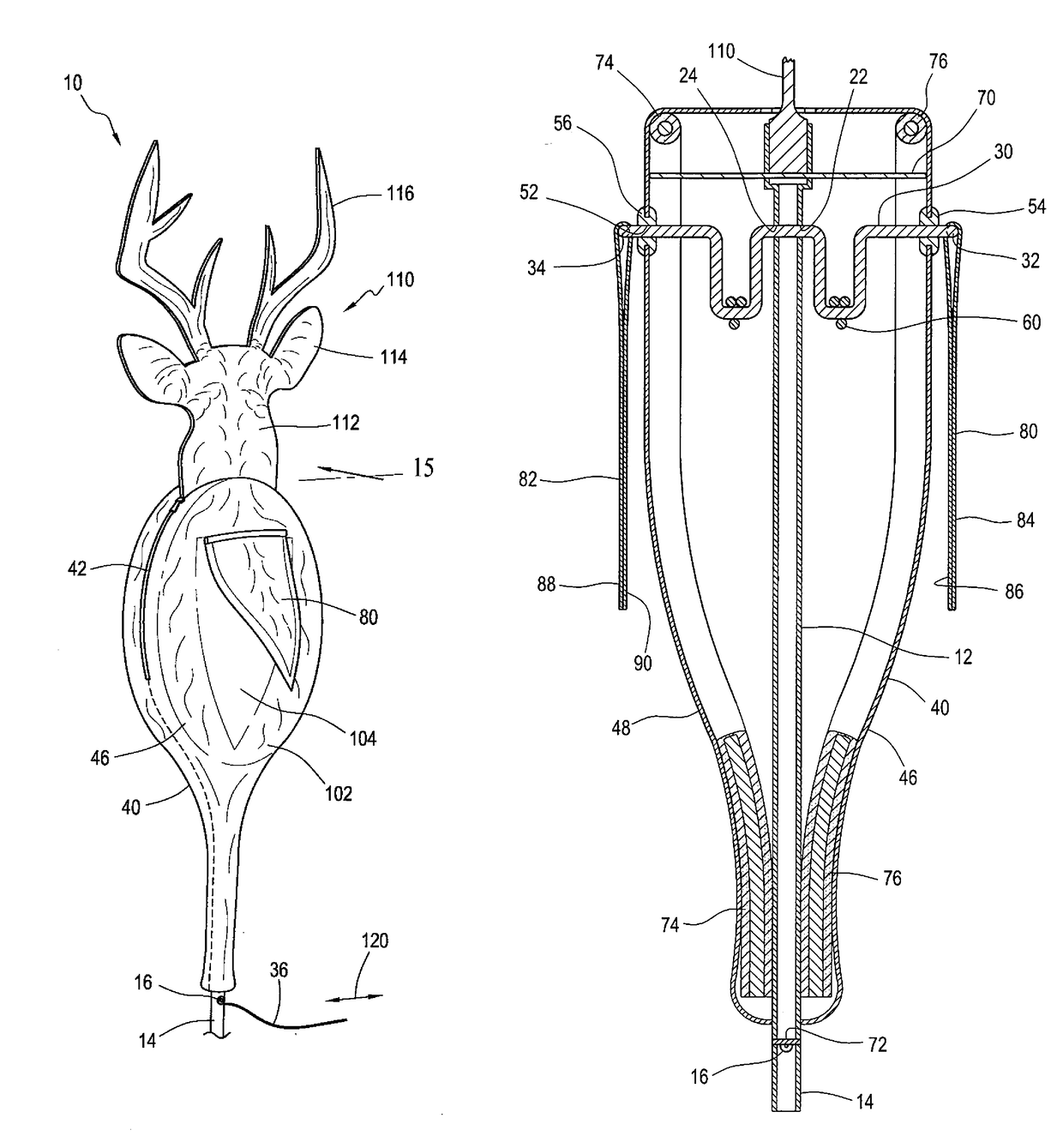
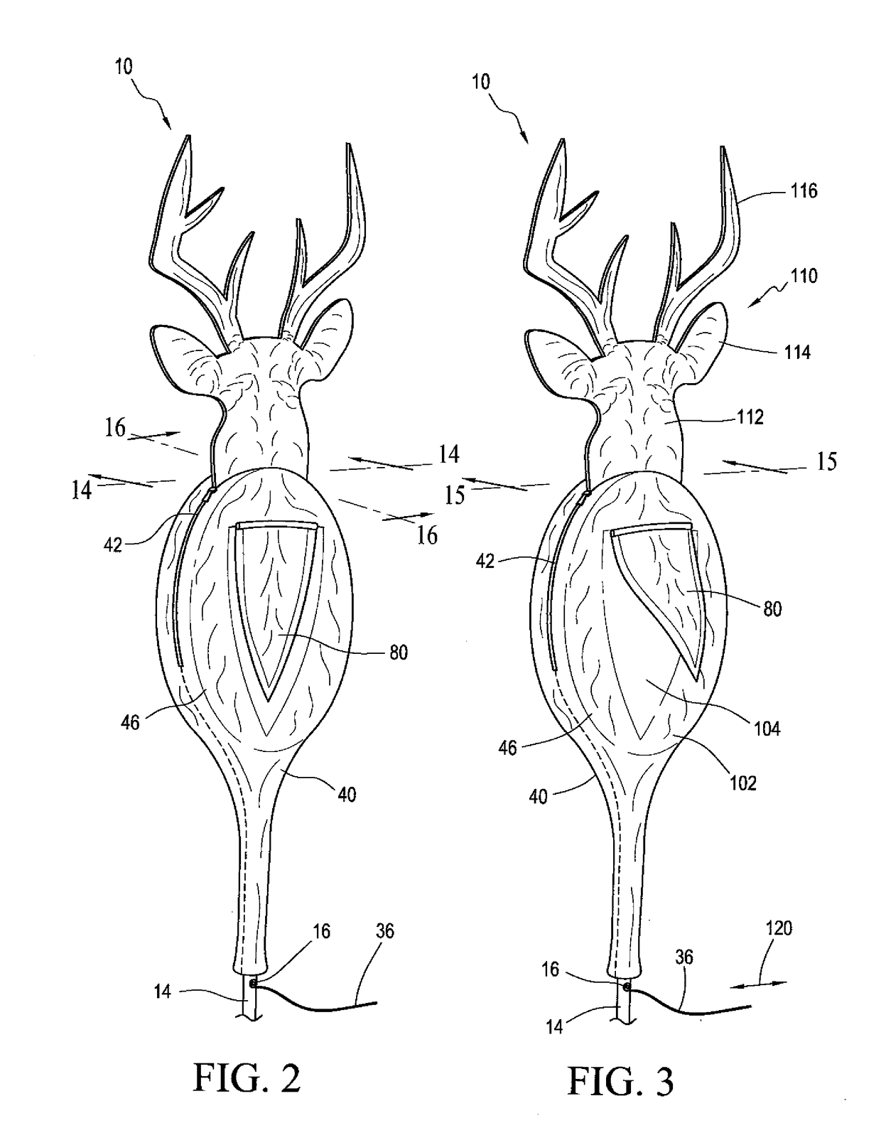
[0037]Referring to FIG. 1, a deer hunting decoy 10 is shown staked into the ground at the edge of a stand of trees and at a distance spaced apart from a hunting blind 160. A pull cord 36 extends from the deer hunting decoy 10 to the hunting blind 160. A hunter positioned within the hunting blind 160 may pull on the pull cord 36 to cause rotational tail movement of the deer hunting decoy 10.

[0038]Referring next to FIGS. 2, 3, 9, 12, 13, 14, 15 and 16, the deer hunting decoy 10 has a central tube 12 extending vertically within the inside volume of the deer hunting decoy 10. The central tube 12 has a stake end 14 at its bottom or distal end and a shoulder 18 at its top or proximal end. At least one hole 16 is formed through the sidewall of the central tube 12 at or near its stake end 14. At least one first hole 22 and one second hole 24 are formed through the sidewall of the central tube at or near its top or proximal end.

[0039]The central tube 12 is rigid or substantially rigid, and m...


PUM


Abstract

A deer hunting decoy has a central post within a flexible cover having front and rear faces with coloration simulating the hind quarters of a deer, with each including a lighter colored central portion surrounded by a darker colored border. The lighter colored central portions are covered by tail flaps. The tail flaps are joined for rotational movement to an axle that extends across the central post and through holes in the flexible cover. A pull cord is directly or indirectly joined to the axle. Tugging the pull cord causes rotation of the axle and movement of the tail flaps to simulate tail movement of a deer. The central post is staked to a ground. Different decoy deer heads are interchangeably attachable. A buck head silhouette terminates in a tube connector that releasable fits within a proximal end of the central post. A grazing doe silhouette has a hook portion at one end and a doe head at the opposite end. The hook portion is inserted over an edge of an opening in the flexible cover and the head portion is pinned to the ground.

Description

FIELD OF THE INVENTION[0001]The present invention relates to a hunting decoy especially configured for attracting white tail deer to a hunter's location by visual stimulus.BACKGROUND OF THE INVENTION[0002]Hunters use various methods to attract white tail deer to the hunter's location. In a first instance, scents and sounds can be used to lure deer to a vicinity. Such methods often are deficient because the deer do not approach the hunters location within shooting distance without additional visual confirmation of the presence of other animals.[0003]White tail deer use their tails as a visual means of communicating with other deer. For example, does will raise their tails to signal that they are ready to breed. Bucks recognize and are attracted to a doe's tail raising display. Accordingly, visual attractors (decoys) have been proposed for hunting white tail deer.[0004]U.S. Pat. No. 5,791,081 is a deer tail decoy that can be affixed to a heavy, full-sized deer body decoy structure. Th...

Claims


Application Information

Patent Timeline
IPC IPC(8): A01M31/06A01M31/00
CPCA01M31/06A01M31/004
Inventor ORR, STEPHEN A.BASHER, W. WARREN
Owner MCWHORTER PAULA
Why Eureka
Try Eureka