
Weight distributing and sway control hitch

a trailer and sway control technology, applied in the direction of towing devices, vehicle components, transportation and packaging, etc., can solve the problems of reducing steering control, raising the cam change or shortening the longitudinal spacing of the cam follower behind the ball mount, and reducing steering control

Active Publication Date: 2021-06-29
B & W CUSTOM TRUCK BEDS
View PDF33 Cites 6 Cited by
  • Summary
  • Abstract
  • Description
  • Claims
  • Application Information

AI Technical Summary

Benefits of technology

This solution provides a more efficient and cost-effective method for adjusting the weight distribution hitch to counteract different trailer loads, preventing uncontrolled swaying while simplifying the installation and adjustment process, thereby enhancing steering control and reducing operational complexity.

Problems solved by technology

Because rear receiver hitches or bumper hitches are mounted in spaced relation behind the rear axle, the weight of a loaded trailer bearing down on the hitch functions to raise the front end of the vehicle and front wheels relative to the rear wheels which reduces steering control.
Swaying of the trailer relative to the towing vehicle also reduces steering control.
However, raising the cam changes or shortens the longitudinal spacing of the cam follower behind the ball mount.
Other known weight distributing hitches require unbolting and sliding of a mounting bracket for each support surface for the spring arms to adjust the position of the support surfaces relative to the spring arms which can be difficult and time consuming.
Although the length adjustable cam support arm disclosed in U.S. Pat. No. 6,419,257 is generally easier to adjust than unbolting and sliding mounting brackets as in other existing weight distributing hitches, the additional components required add to the cost of the product and increase installation time.

Method used


Image

  • Weight distributing and sway control hitch
  • Weight distributing and sway control hitch
  • Weight distributing and sway control hitch

Examples


Embodiment Construction

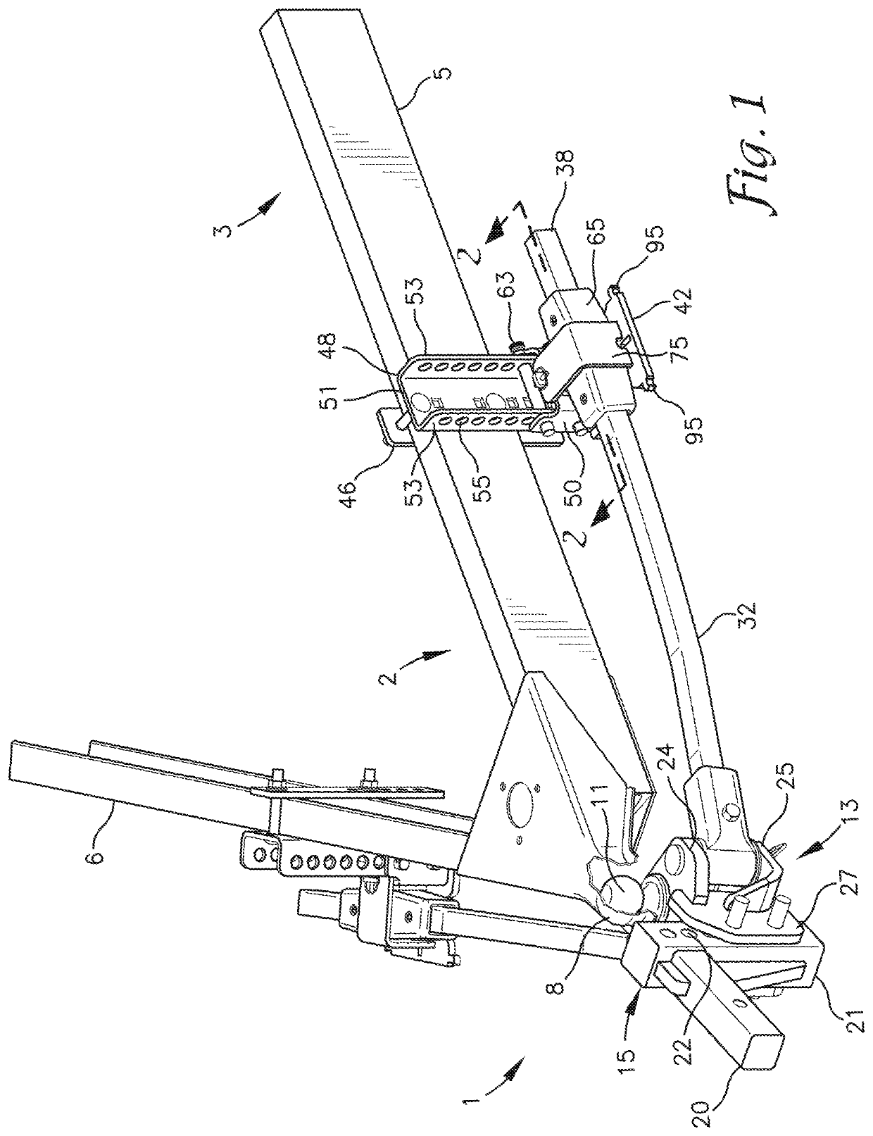
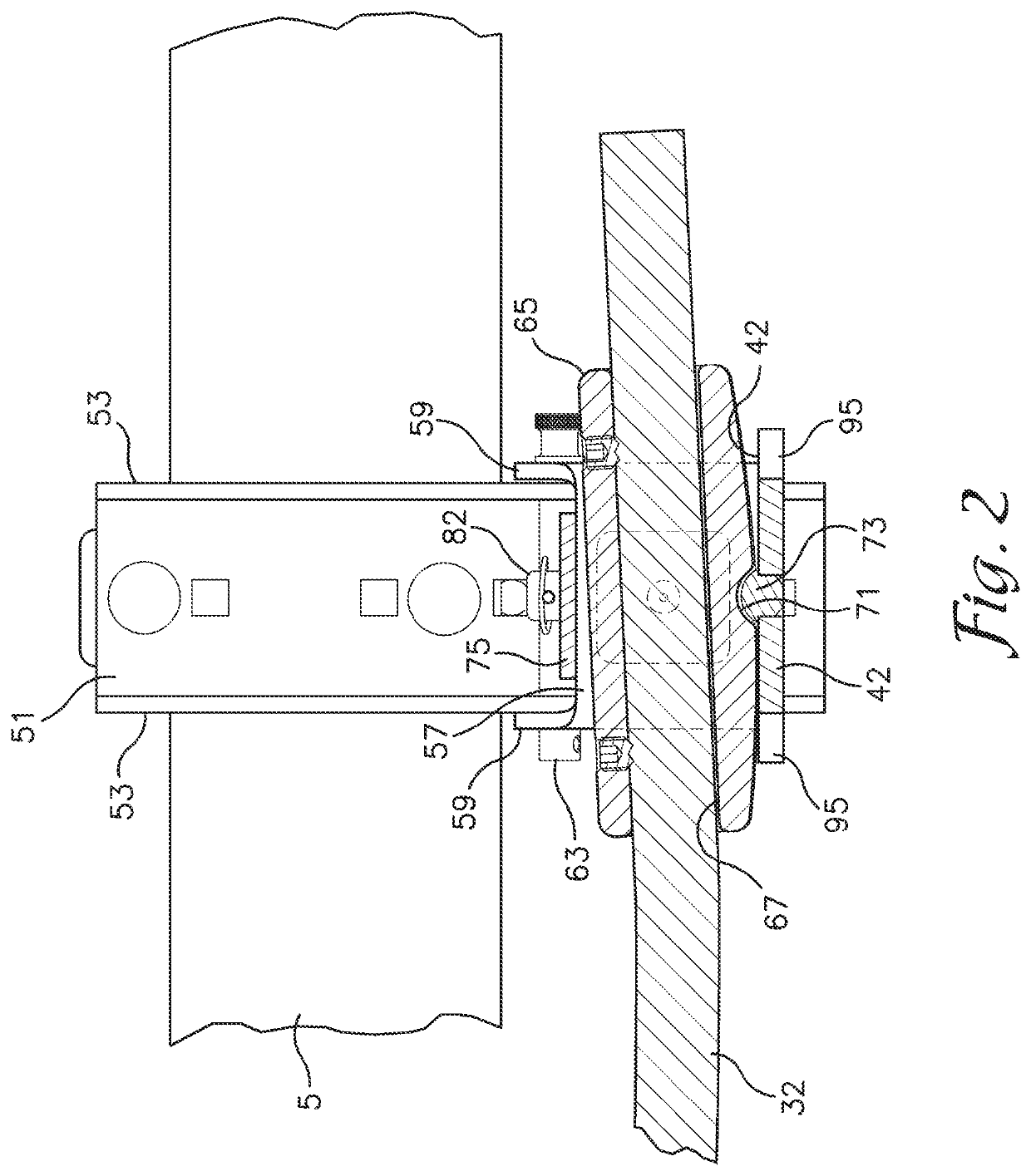
[0032]As required, detailed embodiments of the present invention are disclosed herein; however, it is to be understood that the disclosed embodiments are merely exemplary of the invention, which may be embodied in various forms. Therefore, specific structural and functional details disclosed herein are not to be interpreted as limiting, but merely as a basis for the claims and as a representative basis for teaching one skilled in the art to variously employ the present invention in virtually any appropriately detailed structure. The drawings constitute a part of this specification and include exemplary embodiments of the present invention and illustrate various objects and features thereof.

[0033]Referring to FIGS. 1 through 4 and 7 through 11, a weight distributing hitch assembly 1 is shown which is used to connect a trailer 2 to a towing vehicle 3 (see FIG. 7). The trailer 2 is typically of the type having two frame members or frame rails 5 and 6 connected to and extending rearward...


PUM


Abstract

A weight distributing hitch for towing a trailer includes a pair of deflection bars extending rearward from a ball mount head. A distal end of each deflection bar is supported by a deflection bar support connected to the frame by a height adjustable bracket assembly. A first resistance feature on the deflection bar support engages a second resistance feature associated with the deflection bar to restrain the deflection bar from sliding relative to the deflection bar support and thereby preventing swaying of the trailer relative to the towing vehicle. A longitudinal position of the second resistance feature relative to the deflection bar or a longitudinal position of the first resistance feature relative to said deflection bar supported by said deflection bar support is adjustable to position the second resistance feature in engagement with the first resistance feature when the deflection bar is supported on the deflection bar support.

Description

[0001]This application claims the benefit of U.S. Provisional Application Ser. No. 62 / 659,467, entitled Weight Distributing and Sway Control Hitch, filed Apr. 18, 2018, the disclosure of which is hereby incorporated herein in its entirety by reference.BACKGROUND OF THE INVENTIONField of the Invention[0002]The present invention relates generally to weight distributing and sway control trailer hitches.Background of the Invention[0003]The increased utilization of rear receiver hitches or bumper hitches for towing trailers has increased the demand for weight distributing hitches which are also designed to prevent uncontrolled swaying of the trailer relative to the towing vehicle. Gooseneck or fifth wheel hitches are typically mounted just forward of a rear axle of a pick-up truck and thereby help distribute the load more evenly relative to the towing vehicle. Because rear receiver hitches or bumper hitches are mounted in spaced relation behind the rear axle, the weight of a loaded trail...

Claims


Application Information

Patent Timeline
Patent Type & Authority Patents(United States)
IPC IPC(8): B60D1/34B60D1/24B60D1/167B60D1/06
CPCB60D1/247B60D1/06B60D1/167B60D1/345B60D1/58
Inventor MCCALL, TRAVIS M.JELINEK, TYLER
Owner B & W CUSTOM TRUCK BEDS
Learn More