Vacuum valve and valve control device

a vacuum valve and control device technology, applied in the direction of fluid pressure control, process and machine control, instruments, etc., can solve the problem of insufficient fine adjustment performance of the opening degree of the valve body, and achieve the effect of improving the fine adjustment performance of the vacuum valve configured to drive the valve body up and down

Active Publication Date: 2021-06-15
SHIMADZU CORP
View PDF10 Cites 7 Cited by
  • Summary
  • Abstract
  • Description
  • Claims
  • Application Information

AI Technical Summary

Benefits of technology

[0019]According to the present invention, fine adjustment performance of a vacuum valve configured to drive a valve body up and down can be improved.

Problems solved by technology

However, in the vacuum valve configured to control opening / closing of the valve body by the feed screw drive method, there is a problem that valve body opening degree fine adjustment performance is insufficient due to backlash of a feed screw mechanism.

Method used


Image

  • Vacuum valve and valve control device
  • Vacuum valve and valve control device
  • Vacuum valve and valve control device

Examples


Embodiment Construction

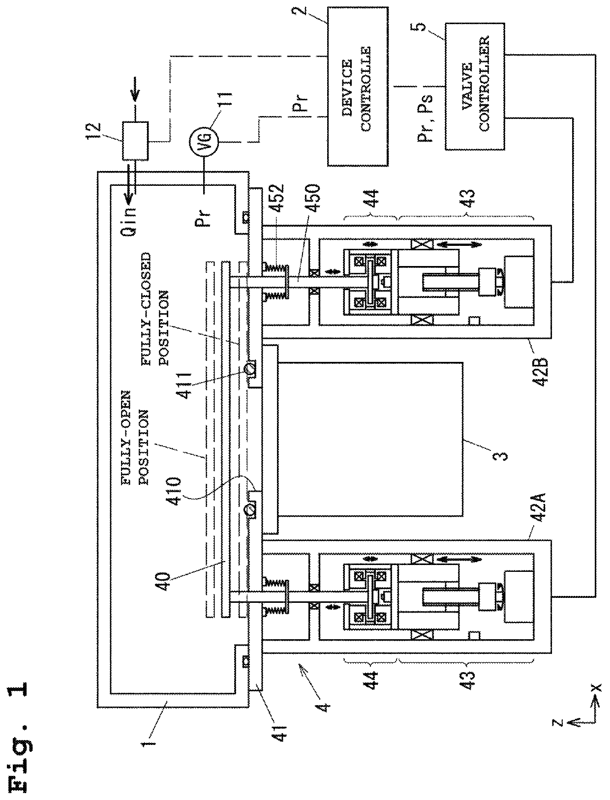
[0032]Hereinafter, an embodiment of the present invention will be described with reference to the drawings. FIG. 1 is a view of one embodiment of a vacuum valve according to the present invention, and is a view of an outline configuration of a vacuum device attached to a vacuum valve 4. The vacuum device includes a vacuum chamber 1 in which a vacuum process is performed, and a device controller 2 configured to perform control regarding processing in the vacuum chamber 1.

[0033]A vacuum pump 3 configured to vacuum-pump gas from the vacuum chamber 1 and the vacuum valve 4 configured to adjust an effective pumping speed upon vacuum pumping of the vacuum chamber 1 are attached to the vacuum chamber 1. For example, a turbo-molecular pump is used as the vacuum pump 3. The operation of opening / closing the vacuum valve 4 is controlled by a valve controller 5. The internal pressure (hereinafter referred to as a “pressure measurement value”) Pr of the vacuum chamber 1 is measured by a vacuum m...


PUM


Abstract

A vacuum valve for driving a valve body arranged facing a valve opening up and down relative to the valve opening to perform valve opening / closing operation, comprises: a first up-down driver configured to drive the valve body up and down with a first minimum drivable amount; and a second up-down driver configured to drive the valve body up and down with a second minimum drivable amount smaller than the first minimum drivable amount.

Description

BACKGROUND OF THE INVENTION1. Technical Field[0001]The present invention relates to a vacuum valve and a valve control device.2. Background Art[0002]Typically, a poppet vacuum valve configured to control a flow rate has been known (see, e.g., Patent Literature 1 (JP-A-2017-227325)). In the vacuum valve described in Patent Literature 1, a valve body is driven up and down relative to a valve seat to control a valve body opening degree. For example, a feed screw drive method as in a technique described in Patent Literature 2 (JP-A-2001-304173) has been generally known as a valve body drive method. In the technique described in Patent Literature 2, a threaded rod screwed into a ball screw nut fixed to a valve rod is rotatably driven by, e.g., a stepping motor to drive a valve body fixed to the valve rod up and down.[0003]In a vacuum process of a semiconductor manufacturing device, an automatic pressure adjustment vacuum valve configured to automatically adjust the pressure of a vacuum c...

Claims


Application Information

Patent Timeline
Patent Type & Authority Patents(United States)
IPC IPC(8): F16K31/06F16K31/04F16K31/02G05D16/20F16K41/10F16K37/00
CPCF16K31/02F16K31/04F16K31/0655F16K31/0675F16K37/005F16K41/10G05D16/202Y10T137/7761F16K1/00F16K51/02F16K31/508F16K37/0041F16K31/0679G05D16/024
Inventor KOZAKI, JUNICHIRO
Owner SHIMADZU CORP
Why Eureka
Try Eureka