
Refillable wiper blade with refill subassembly

a refillable, wiper blade technology, applied in vehicle maintenance, vehicle cleaning, transportation and packaging, etc., can solve the problems of affecting the performance of the wiper blade, the expected deterioration, and the exacerbated wear and deterioration of certain operating conditions, so as to achieve the effect of cleaning a surface and simple releasable attachment to the wiper arm

Active Publication Date: 2021-05-25
TRICO PROD CORP
View PDF15 Cites 0 Cited by
  • Summary
  • Abstract
  • Description
  • Claims
  • Application Information

AI Technical Summary

Benefits of technology

The present invention is an adapter and wiper blade that work together to effectively clean a surface. It is also easy to attach to a wiper arm. This invention has advantages in manufacturing and component assembly.

Problems solved by technology

Indeed, wiper blades generally perform best when new and are expected to deteriorate over time, such as due to friction occurring between the wiping element and the surface to be wiped.
In addition, wear and deterioration can be exacerbated by certain operating conditions, such as frequency and duration of use, environmental temperature fluctuations, exposure to abrasive materials (for example, dust, dirt, mud, leaves, and the like), and / or exposure to contaminants (for example, automotive cleaning agents, organic material from bug-splatter or bird droppings, and the like).
Moreover, there is a tendency for consumers to replace wiper blades only after a significant decrease in wiping performance, as opposed to replacing the wiper blades as soon as wiping quality begins to deteriorate.
Indeed, consumers often replace wiper blades as-needed as opposed to at regularly-scheduled intervals, in particular where rain is infrequent or sporadic.

Method used


Image

  • Refillable wiper blade with refill subassembly
  • Refillable wiper blade with refill subassembly
  • Refillable wiper blade with refill subassembly

Examples


Embodiment Construction

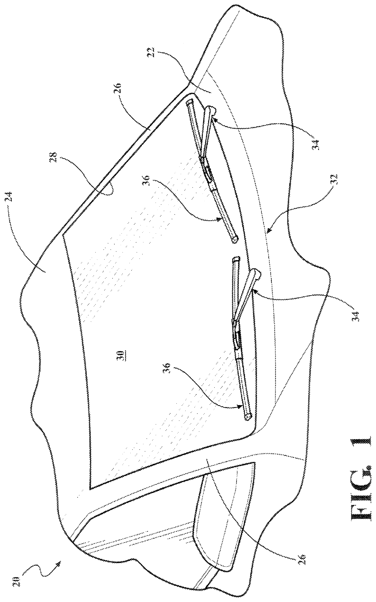
[0025]With reference to the Figures, where like numerals are used to designate like a corresponding structure throughout the several views, a portion of a vehicle is schematically illustrated at 20 in FIG. 1. The vehicle 20 includes a cowl 22, a roof 24, and a pair of laterally spaced front A-pillars 26 extending between the roof 24 and the cowl 22. The A-pillars 26, roof 24, and cowl 22 cooperate to define a generally rectangular opening 28 in which a curved or “swept back” glass windshield 30 is supported. As illustrated, the vehicle 20 is an automobile, but could be any type of vehicle, such as a heavy-duty truck, train, airplane, ship, construction vehicle or equipment, military vehicle, or any other type of vehicle that utilizes surface wiper systems.

[0026]A wiper system is generally indicated at 32 in FIG. 1 and is employed to clean the windshield 30. The wiper system 32 includes a pair of wiper arms, generally indicated at 34, and a pair of wiper blades, generally indicated a...


PUM


Abstract

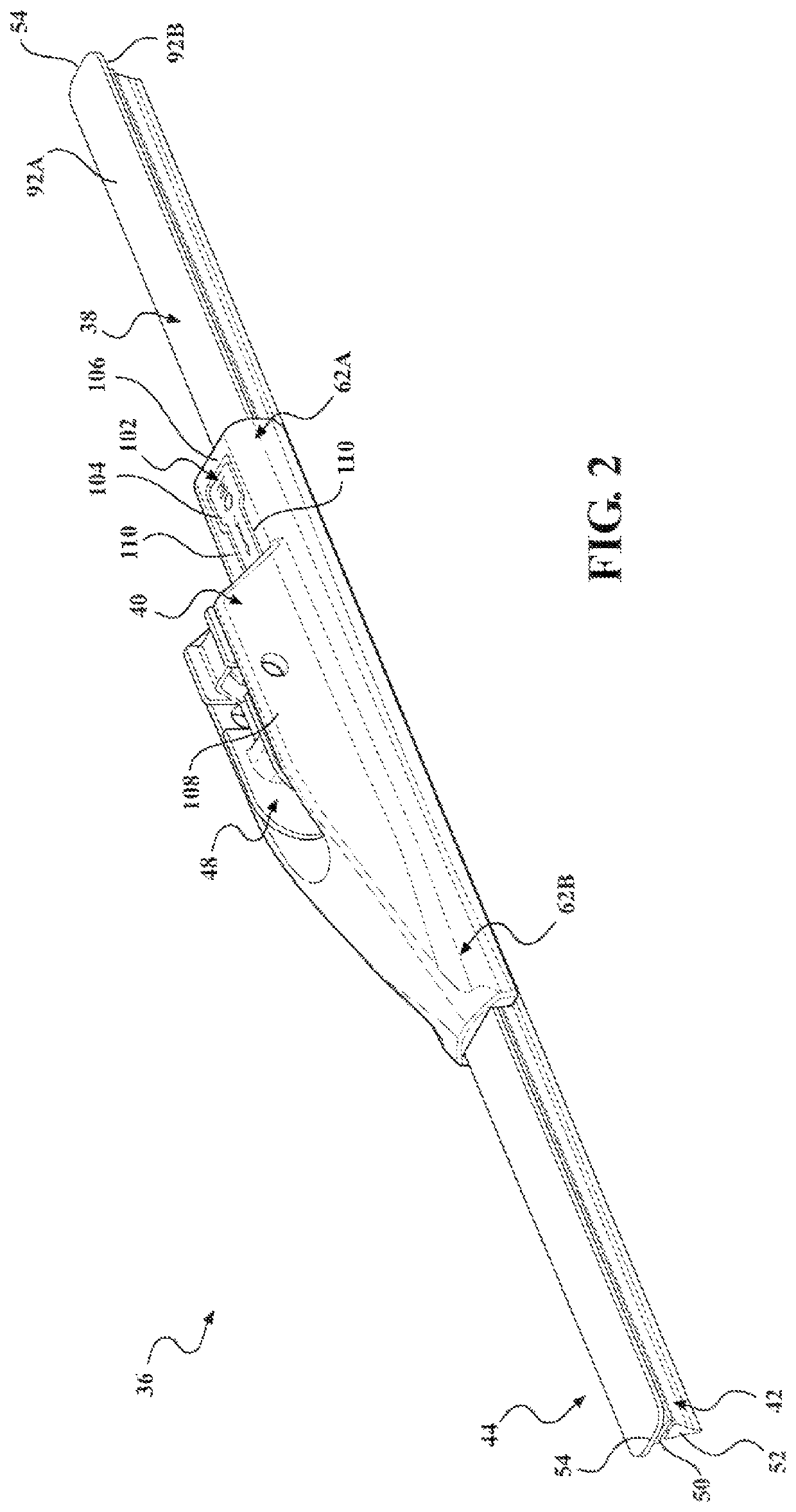
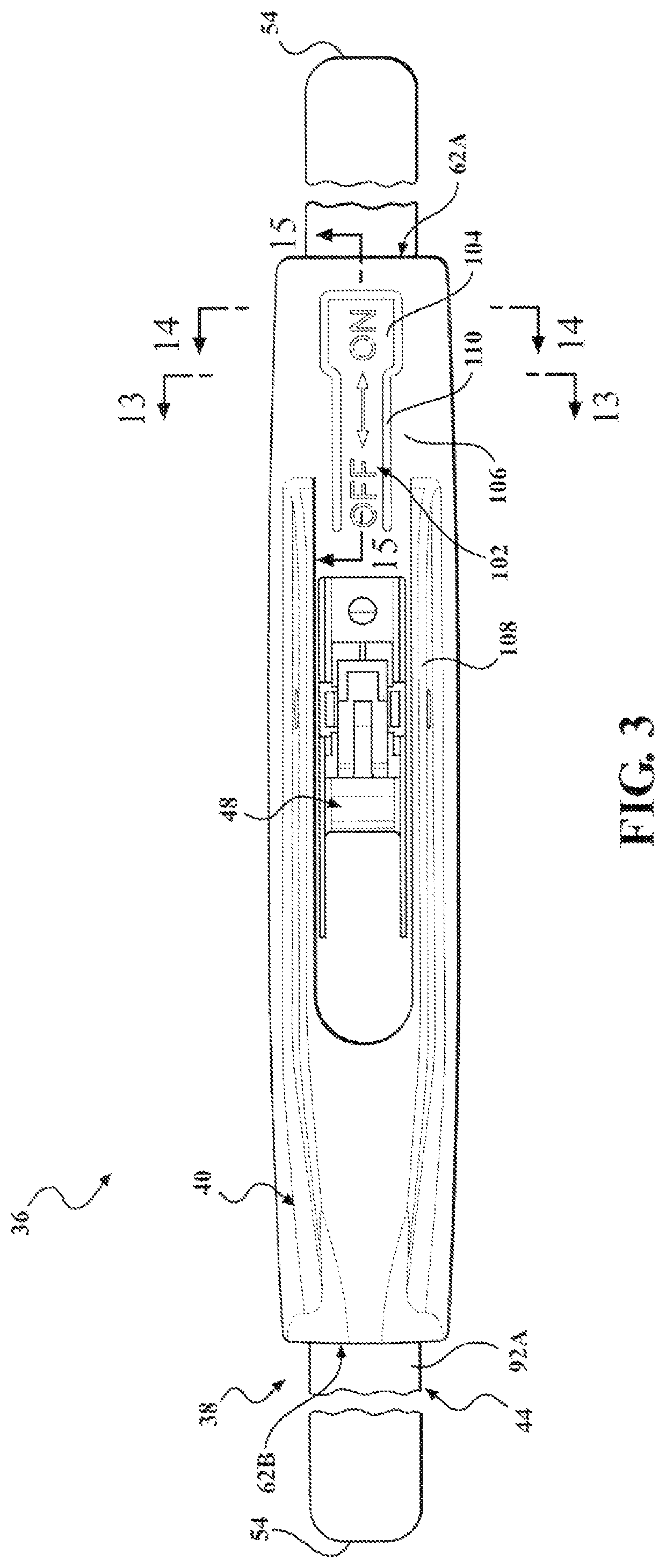
A refillable wiper blade (36) including a refill subassembly (38) and a coupler (48) adapted for releasable attachment thereto. The refill subassembly includes a wiping element (42), an elongated spline (44) supporting the element, and a retention clip (46) operatively attached to the spline. The clip has a body (58) and an upwardly-biased cantilevered finger (60) extending from the body. The coupler has a first end (62A) shaped to receive the body of the clip, and a relief (64) defined adjacent to the first end and shaped to accommodate the finger of the clip. The refill subassembly and the coupler cooperate such that predetermined movement of the coupler with respect to the refill subassembly brings the body into engagement with the first end of the coupler such that the finger deflects downwardly until subsequent movement of the coupler along the spline releases the finger upwardly and into the relief of the coupler thereby securing the refill subassembly to the coupler.

Description

CROSS-REFERENCE TO RELATED APPLICATIONS[0001]This application claims priority to and all the benefits of U.S. Provisional Application No. 62 / 249,666, filed on Nov. 2, 2015.BACKGROUND OF THE INVENTION1. Field of the Invention[0002]The present invention relates, generally, to wiper blades and, more specifically, to a refillable wiper blade with a refill subassembly.2. Description of the Related Art[0003]Conventional automotive wiper systems known in the art typically include some type of wiper blade (sometimes referred to as a “wiper blade assembly” or “wiper assembly”) mounted to a wiper arm which, in turn, is mounted adjacent to a surface to be wiped, such as a windshield of a vehicle, and pivotally driven to impart reciprocal motion to the wiper blade across the windshield. The wiper blade typically includes a rubber wiping element that contacts the windshield across the surface to be wiped. Modern wiper blades often incorporate one or more metal strips that act to reinforce the wi...

Claims


Application Information

Patent Timeline
Patent Type & Authority Patents(United States)
IPC IPC(8): B60S1/38B60S1/40
CPCB60S1/3851B60S1/3856B60S1/3863B60S1/387B60S1/4009
Inventor AVASILOAIE, VALENTINPOLOCOSER, MITICA
Owner TRICO PROD CORP
Learn More