
Battery pack system for electrically connecting a battery pack to a machine

a battery pack and machine technology, applied in the field of batteries, can solve the problems of increasing the risk of fire erupting, affecting the safety of the battery pack, and the outcome of the fire may be catastrophic, and the solution is considered to be too complicated and costly

Active Publication Date: 2021-03-30
DEFOND ELECTECH CO LTD
View PDF26 Cites 2 Cited by
  • Summary
  • Abstract
  • Description
  • Claims
  • Application Information

AI Technical Summary

Benefits of technology

The present invention provides a system that minimizes the risk of injury or damage to battery packs caused by inadvertent shorting during storage or shipping. This is achieved through the use of a secondary electrical cut-off switch that automatically closes upon connection with the power tool, eliminating the need for manual re-connection. Additionally, the invention improves efficiency at both the battery pack manufacturing process and the user end, reducing time and labor requirements.

Problems solved by technology

Unfortunately, in view of this increase in the power output capacity of such battery packs, concerns have been raised that there is a greater risk of a fire erupting should the battery terminals be inadvertently short-circuited, for instance, when such battery packs are being stored or shipped.
If the above short-circuit scenario were to occur whilst being shipped on an aeroplane, the outcome may be catastrophic.
However, as this solution requires manual manipulation of the electric circuitry within the battery pack prior to shipping and then manually reconnecting the electrical circuitry within the battery pack again once shipped, such a solution is considered to be unduly complicated and costly.

Method used


Image

  • Battery pack system for electrically connecting a battery pack to a machine
  • Battery pack system for electrically connecting a battery pack to a machine
  • Battery pack system for electrically connecting a battery pack to a machine

Examples


Embodiment Construction

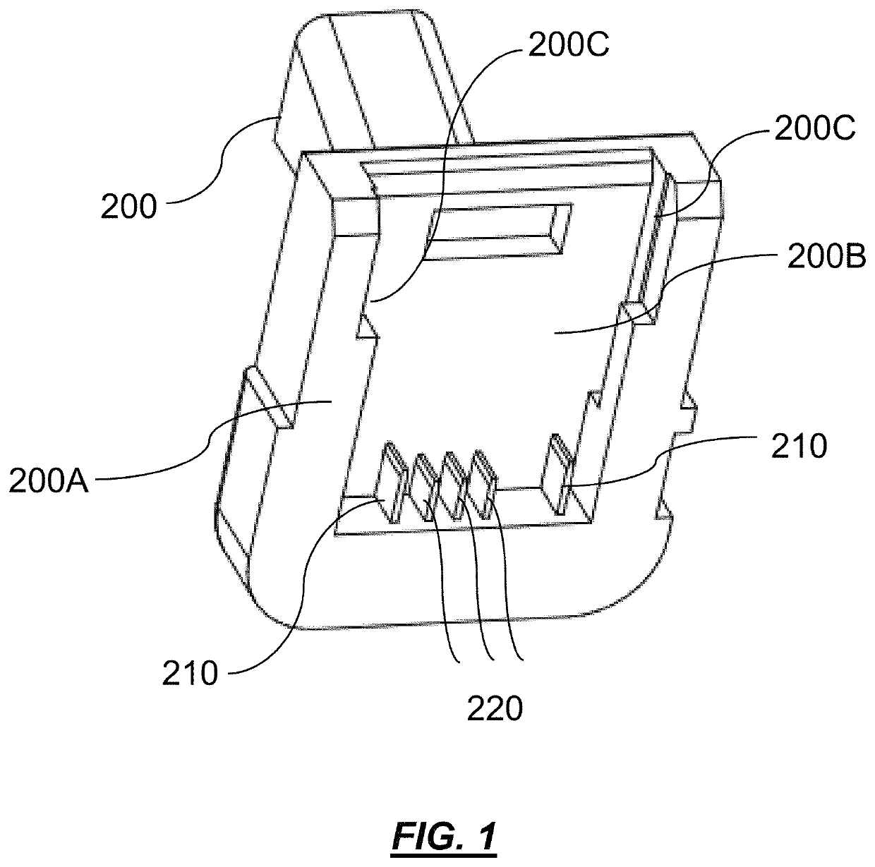
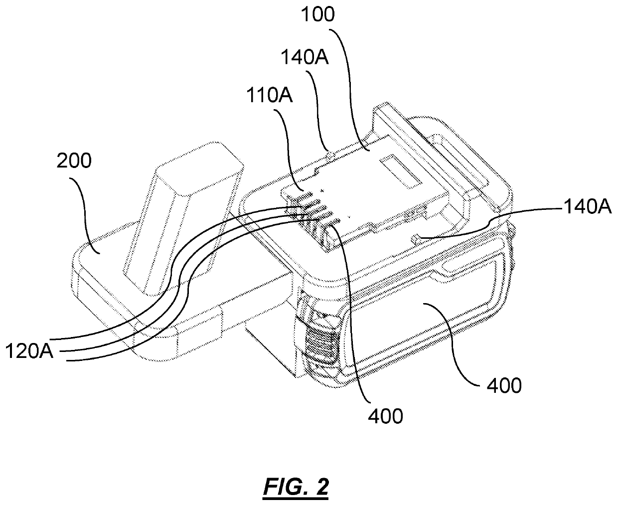
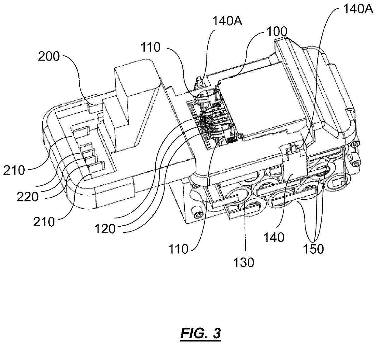
[0095]Preferred embodiments of the present invention will now be described herein with reference to FIGS. 1 to 18. The embodiments include a removable battery pack (100), as well as a system and method for connecting the removable battery pack with a power tool (200). The power tool (200) may include for instance a hand-held electric tool such as a drill having an electric motor for turning a drill bit, although it would be appreciated and understood that this is merely for illustrative purposes and alternate embodiments of the present invention may of course be suitably configured for use in relation to other types of electric power tools such as grinders, sanders, saws, rotary driving tools as well as electric gardening tools and so on. Typically, additional electrical circuitry such as control and over-current circuitry modules, a trigger switch and so on may be located along the electrical circuit path on the power tool between the input power terminals of the power tool and the...


PUM

PropertyMeasurementUnit
poweraaaaaaaaaa
electrical connectivityaaaaaaaaaa
power rating capabilityaaaaaaaaaa

Abstract

A battery pack system for use in connecting a battery pack to a battery pack receiving member of a machine so that the battery pack is operable to supply a suitable amount of power to the machine for operation of the machine via an electrical circuit path that is configurable for electrically connecting the battery pack to the machine, the system including: a first electrical connector member disposed along a first region of the electrical circuit path; and a second electrical connector member; wherein, responsive to the battery pack being connected to the battery pack receiving member of the machine, the second electrical connector member is configured for movement relative to the first electrical connector member to cooperatively form a first configuration which electrically closes the electrical circuit path via which the suitable amount of power is able to be supplied from the battery pack to the machine; and wherein, responsive to the battery pack being disconnected from the battery pack receiving member of the machine, the second electrical connector member is configured for movement relative to the first electrical connector member to cooperatively form a second configuration which electrically opens the electrical circuit path via which the suitable amount of power is not able to be supplied from the battery pack to the machine.

Description

TECHNICAL FIELD[0001]The present invention relates to battery packs, which may include removable battery packs, such as those used in hand-held power tools and the like.BACKGROUND OF THE INVENTION[0002]Hand-held electric power tools and the like typically include a battery receiving compartment via which a battery pack may be attached. Typically the battery pack may be removably connectable with the electric power tool which is convenient in that when the battery pack is faulty and requires replacement or is in need of being recharged, it may be easily removed and replaced by with another battery pack. As the power rating capability of hand-held electric tools has increased over the years, the power output of the battery packs used in such tools has also increased significantly with some battery packs being capable of outputting over 100 Wh in certain cases. Unfortunately, in view of this increase in the power output capacity of such battery packs, concerns have been raised that the...

Claims


Application Information

Patent Timeline
Patent Type & Authority Patents(United States)
IPC IPC(8): H02J7/00B25F5/02H01M2/10H02H7/18H01M2/34H01M50/271H01M50/574
CPCH02J7/0044B25F5/02H01M2/1022H01M2/34H02H7/18H02J7/0042B23B2260/024H01M2200/00H01M2220/30H02J7/0029H02J7/0063H02J2207/20H01M10/42H01M50/574H01M50/271Y02E60/10
Inventor OR, TAK CHUENNIEH, CHENG CHENWONG, KIN YU
Owner DEFOND ELECTECH CO LTD
Learn More