
Interference suppression with mitigation of intermodulation distortion

a technology of interference suppression and intermodulation distortion, applied in the field of interference suppression with mitigation of intermodulation distortion, can solve problems such as the difficulty of receiving low-power signals

Active Publication Date: 2021-03-23
PHOTONICSYST
View PDF9 Cites 1 Cited by
  • Summary
  • Abstract
  • Description
  • Claims
  • Application Information

AI Technical Summary

Benefits of technology

The patent text is discussing the use of photonic systems to improve the reception of low-power signals in the presence of interference. These systems use optical signals to process the RF signals and can provide better performance in terms of wider bandwidth and improved signal fidelity. However, the text recognizes that further improvements are needed to achieve even better results.

Problems solved by technology

A known problem with many RF systems is the challenge of receiving low-power signals in the presence of interference from other higher-power signals.

Method used


Image

  • Interference suppression with mitigation of intermodulation distortion
  • Interference suppression with mitigation of intermodulation distortion
  • Interference suppression with mitigation of intermodulation distortion

Examples


Embodiment Construction

[0010]The present teaching will now be described in more detail with reference to exemplary embodiments thereof as shown in the accompanying drawings. While the present teaching is described in conjunction with various embodiments and examples, it is not intended that the present teaching be limited to such embodiments. On the contrary, the present teaching encompasses various alternatives, modifications and equivalents, as will be appreciated by those of skill in the art. Those of ordinary skill in the art having access to the teaching herein will recognize additional implementations, modifications, and embodiments, as well as other fields of use, which are within the scope of the present disclosure as described herein.

[0011]Reference in the specification to “one embodiment” or “an embodiment” means that a particular feature, structure, or characteristic described in connection with the embodiment is included in at least one embodiment of the teaching. The appearances of the phrase...


PUM


Abstract

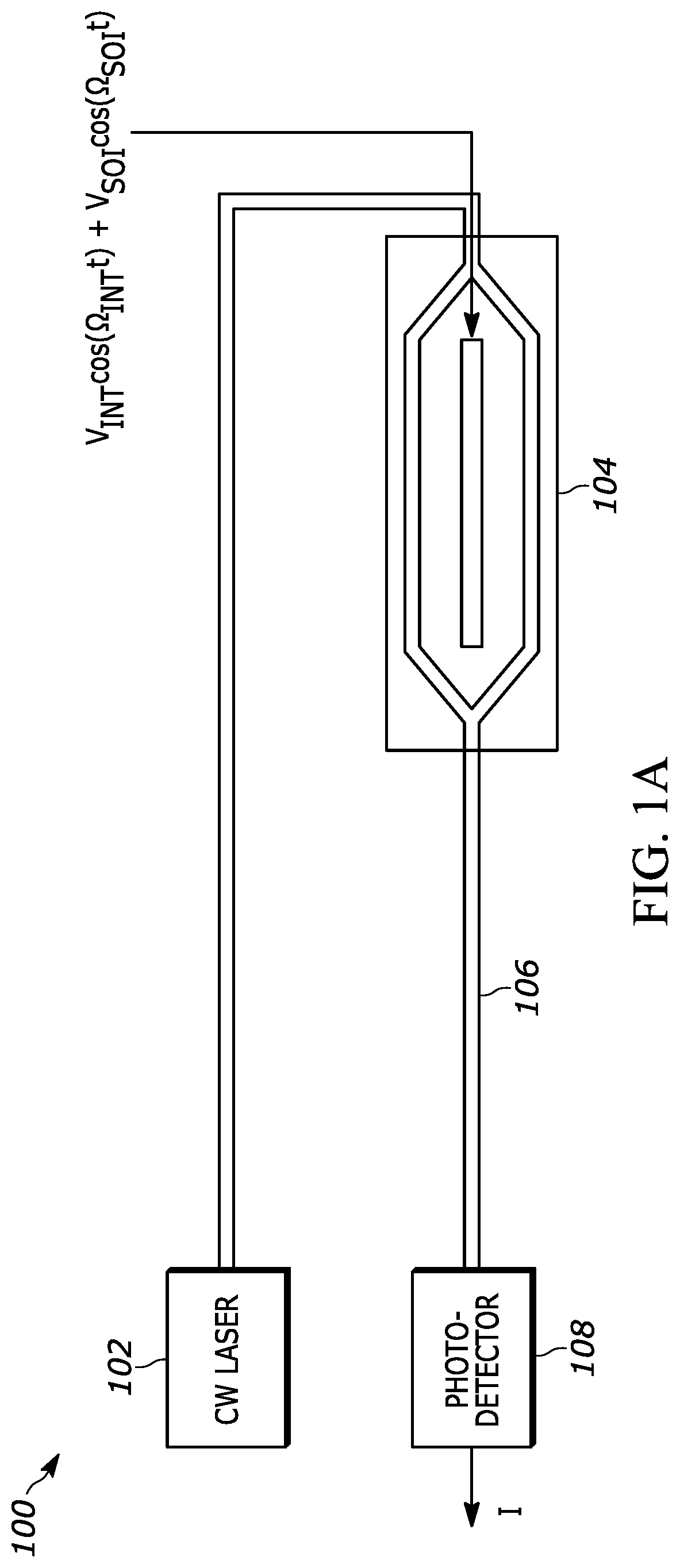
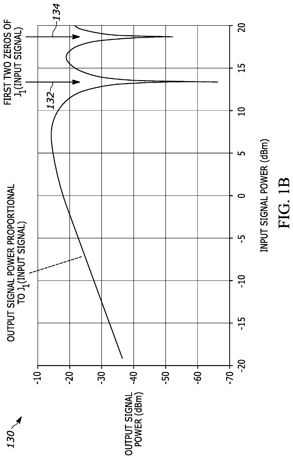
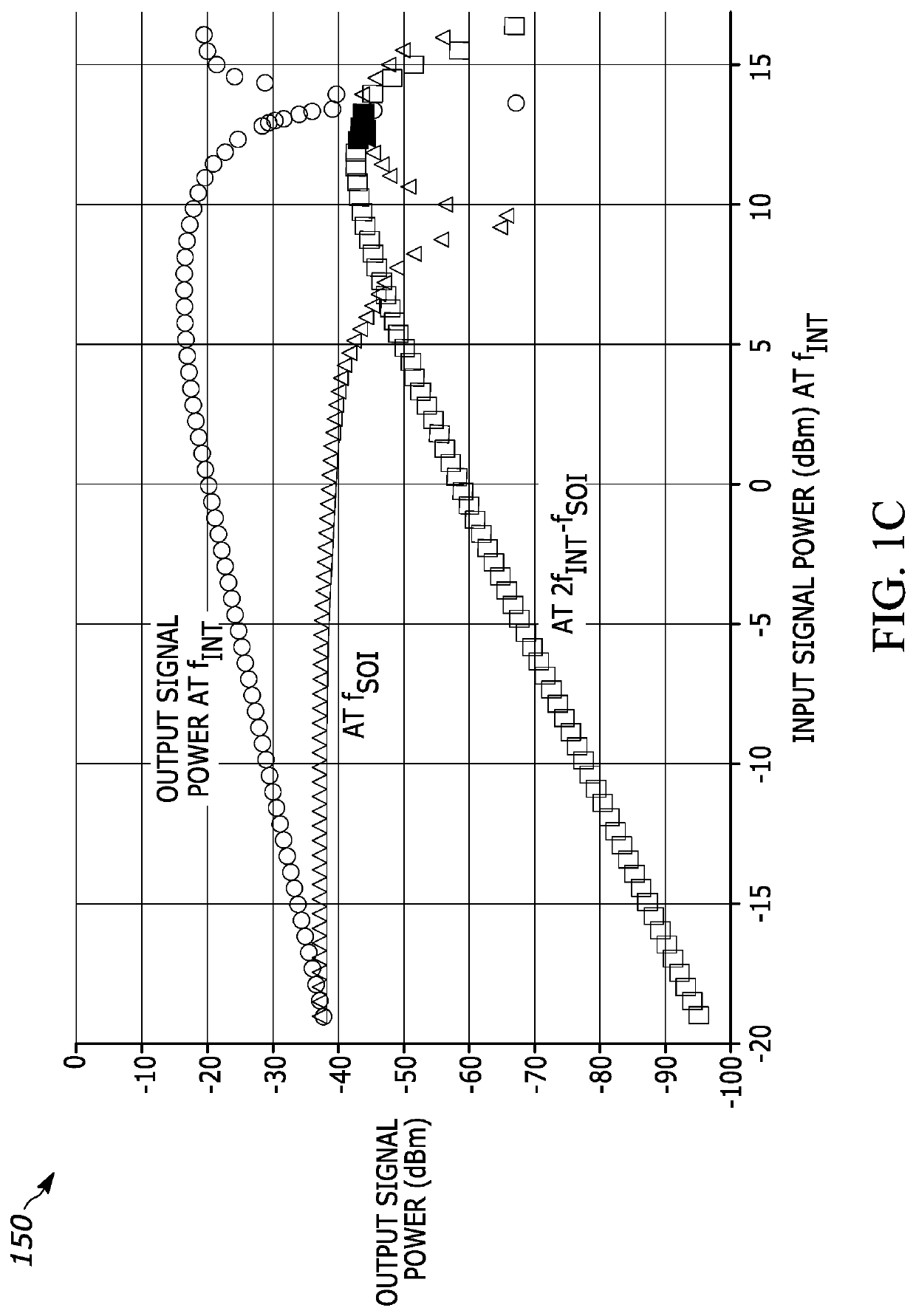
A method of interference suppression with intermodulation distortion mitigation includes processing an RF signal comprising an RF signal of interest and an RF interfering signal to produce a first and second RF drive signal each with a desired RF interference signal power and having a 90 degree relative phase. The first RF drive signal is imposed onto a first optical signal with a modulator to generate a first modulated optical signal so that the modulator has a large-signal behavior that is characterized by a Bessel function of the first kind J1(ϕ), wherein the desired power at a frequency of the interference signal of the first drive signal is chosen to correspond to a zero of the Bessel function of the first kind J1(ϕ). The second RF drive signal is imposed onto a second optical signal with a modulator to generate a second modulated optical signal so that the modulator has a large-signal behavior that is characterized by a Bessel function of the first kind J1(ϕ), wherein the desired power at a frequency of the interference signal of the second drive signal is chosen to correspond to another zero of the Bessel function of the first kind J1(ϕ). The first and second modulated optical signal are combined with an optical power ratio that is selected to suppress third-order intermodulation distortion products in an electrical signal generated by detecting the optically combined first and second modulated optical signals.

Description

CROSS REFERENCE TO RELATED APPLICATION[0001]The present application is a non-provisional application of U.S. Provisional Patent Application No. 62 / 868,208, filed on Jun. 28, 2019, entitled “Interference Suppression with Mitigation of Intermodulation Distortion”. The entire contents of U.S. Provisional Patent Application No. 62 / 868,208 are herein incorporated by reference.INTRODUCTION[0002]A known problem with many RF systems is the challenge of receiving low-power signals in the presence of interference from other higher-power signals. The powers and frequencies of both the desired signals and the undesired (interference) signals can cover a wide range of values for many practical applications. It is therefore highly desirable to suppress interference signals over a wide dynamic range of interference signal powers, as well as to suppress interference over a wide RF bandwidth.[0003]Photonic systems have been used to improve the reception of low-power signals in the presence of signif...

Claims


Application Information

Patent Timeline
Patent Type & Authority Patents(United States)
IPC IPC(8): H04B10/2507H04B10/2575H04B10/2543H04B10/50
CPCH04B10/25073H04B10/2507H04B10/2543H04B10/2575H04B10/50572H04B10/50577H04B2210/006H04B2210/25H04B10/00
Inventor ACKERMAN, EDWARD I.
Owner PHOTONICSYST
Learn More